This is a mild winter. December was cold, and January is turning out to be mostly mud and muck. I elect to work on more indoor-ish things.
At home I am working on the two Adlake white-metal fold-down sinks I bought from Dave Varilek. First I completely disassembled them. Then I picked the best base and bowl, filled the tub with very hot water, and started scrubbing with Comet and a rag. Several hours later they look really shiny again. Next, I collected every part needing a gasket into a box and went shopping at Home Depot. Surprisingly, they had nearly everything I need. Then I went to my drill press, and used different sized wire wheels to clean and polish the metal parts. (Tedious, but the results look great. I tend to clean only what I need next.) Next stop: The museum machine shop. 1146's was arranged to be plumbed from the top, while these were plumbed from the bottom. So I have to cut openings for the pipes in the top of the base. After carefully marking the center lines and transferring the outline from the bottom, I used a drill to get the 3/4" radius, then a band saw to cut the straight sides. The supply pipes are drilled and tapped for both top and bottom feed, so I just swung them around.
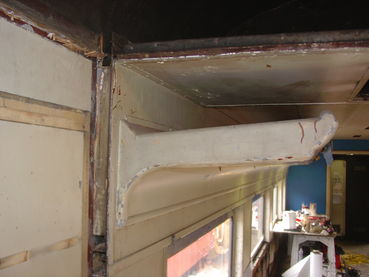
This year I actually went to the annual RPCA conference. (Seems I've always been too broke or too busy at work.) It's a great networking opportunity, but to me the technical seminars are the highlight. Rob Mangles gave a series of excellent talks on passenger car fundamentals, then I took a one day HEP course put on by the RPCA Educational Foundation. Eric Wilde was the instructor. It was spot-on for me - I'm in the process of converting 1146 to HEP. I came away with a copy of the no-longer-available Amtrak Private Car HEP manual, a knowledge of what to do, and a list of things I'd done wrong and need to fix. (Doh!)
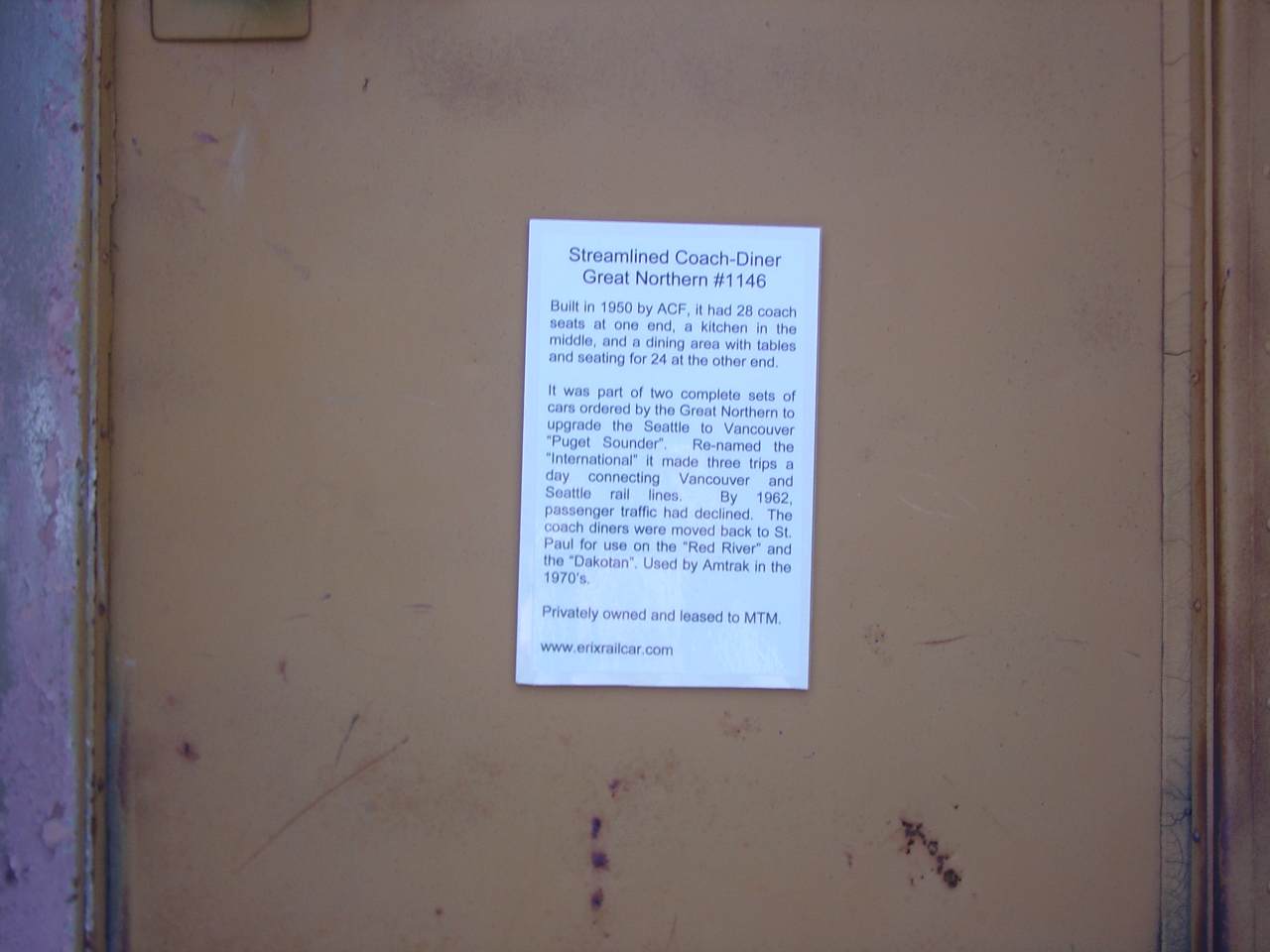
Still working on setting up an account with BNSF, to get 1146 moved to the museum. I need either an e-mail from a non-generic domain (not yahoo.com, for example) or a fax on company letter head. I find it easier to create a web site than a logo, and www.erixrailcar.com is born. This is something I've thought about doing many times, and I'm having a bit of fun with it.
| I had an idea for a logo. Do you like it? It's inspired by the tail sign on a very famous New York to Chicago overnight train. (Yes, I'm a closet fan of the New York Central and their "20th Century Limited") I used this logo on letterhead, which I faxed to the BNSF e-commerce department asking for access with my Yahoo! e-mail address. It did the trick! Now I just need to figure out how to use my new account to submit a waybill. | |
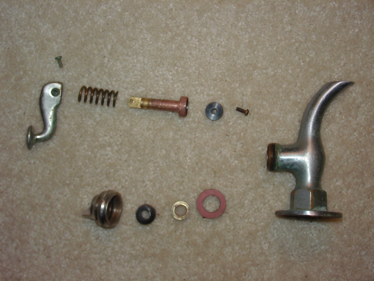
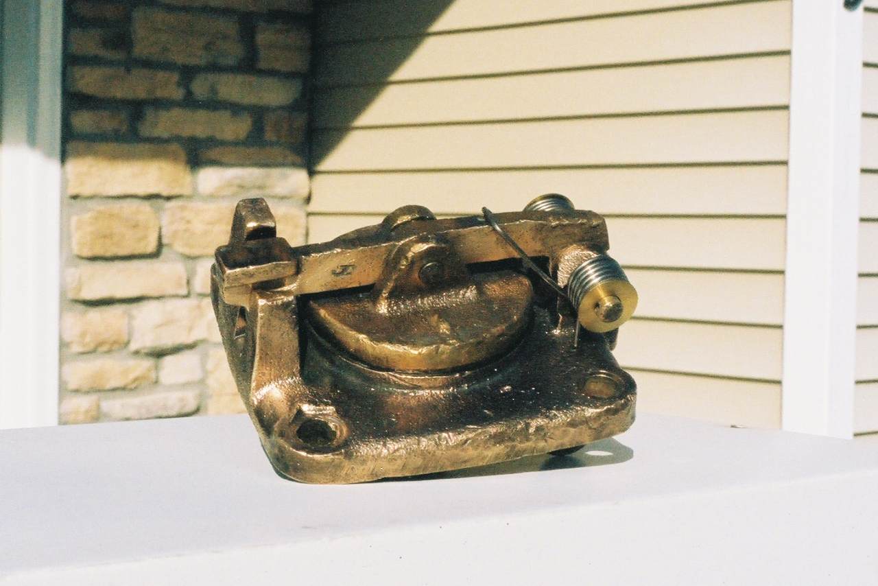
| This is a janitor's faucet I've had on the back burner since last spring. It came from under the lavatory in the men's restroom. I just recently got some new gaskets that will hopefully work, and have been cleaning parts. |
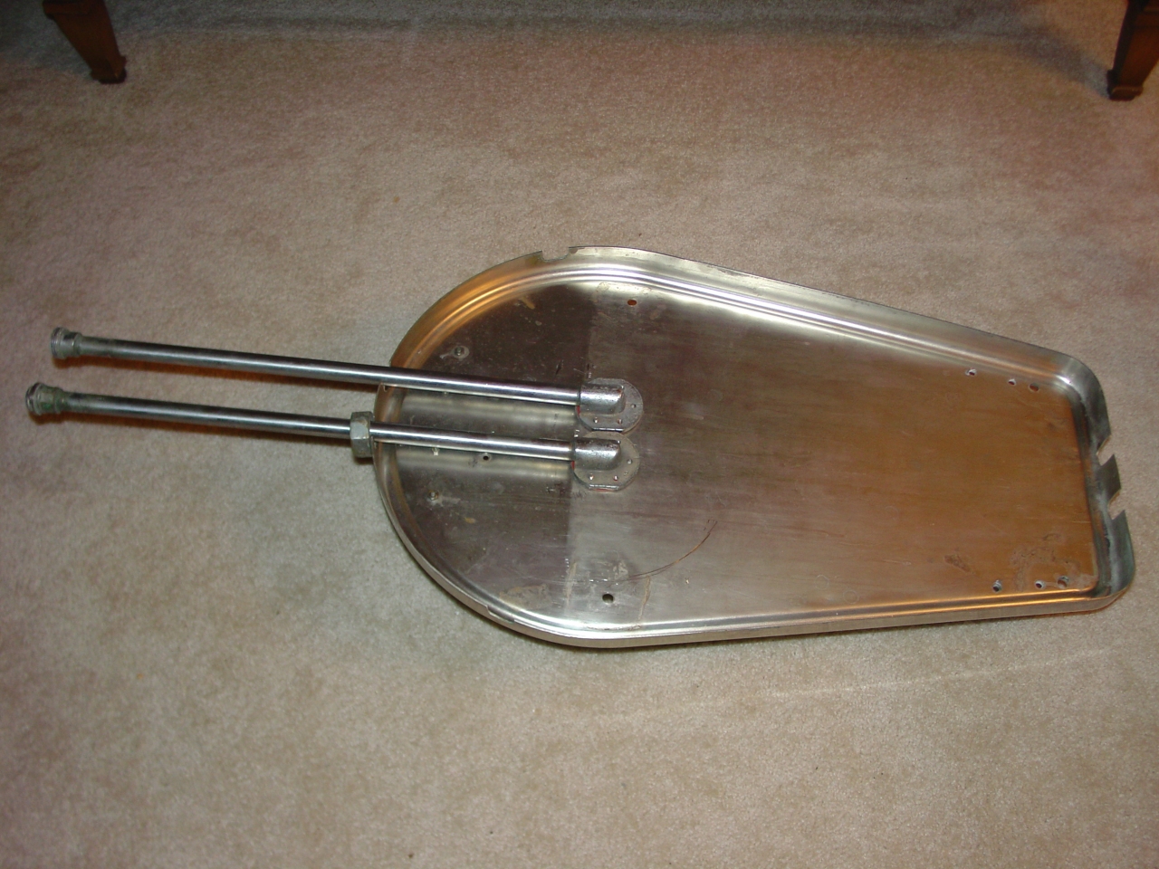
| Here is an Adlake No. 266 white metal folding lavatory, with two separate No. 138 faucets, which I am restoring for the kitchen. It's actually being assembled from three sinks, two from Dave Varilek and one from Bob Moen. I'm cherry-picking the best parts from each. According to the bill of materials, this is identical to the original hand-washing sink which was mounted in the kitchen between the stove and the refrigerator. To get this far, I first completely disassembled all three sinks. (Putting identical parts in labelled zip-lock bags.) Then I picked the best base and bowl, and cleaned them thoroughly with "Bar Keeper's Friend" and piping hot water in my tub. The small metal items I polish with a wire wheel in my drill press. The drain connector at right is a separate piece. After cleaning and installation with new gaskets and plumber's putty, I sealed it and filled the sink with water to test for leaks. After cutting the base in the museum machine shop for piping from the top, I've started mounting hardware. The faucets are half-assembled, waiting for some gaskets to be fitted. Once they're finished and the soap dish is attached, I'll mount the bowl and it will be ready to install. |
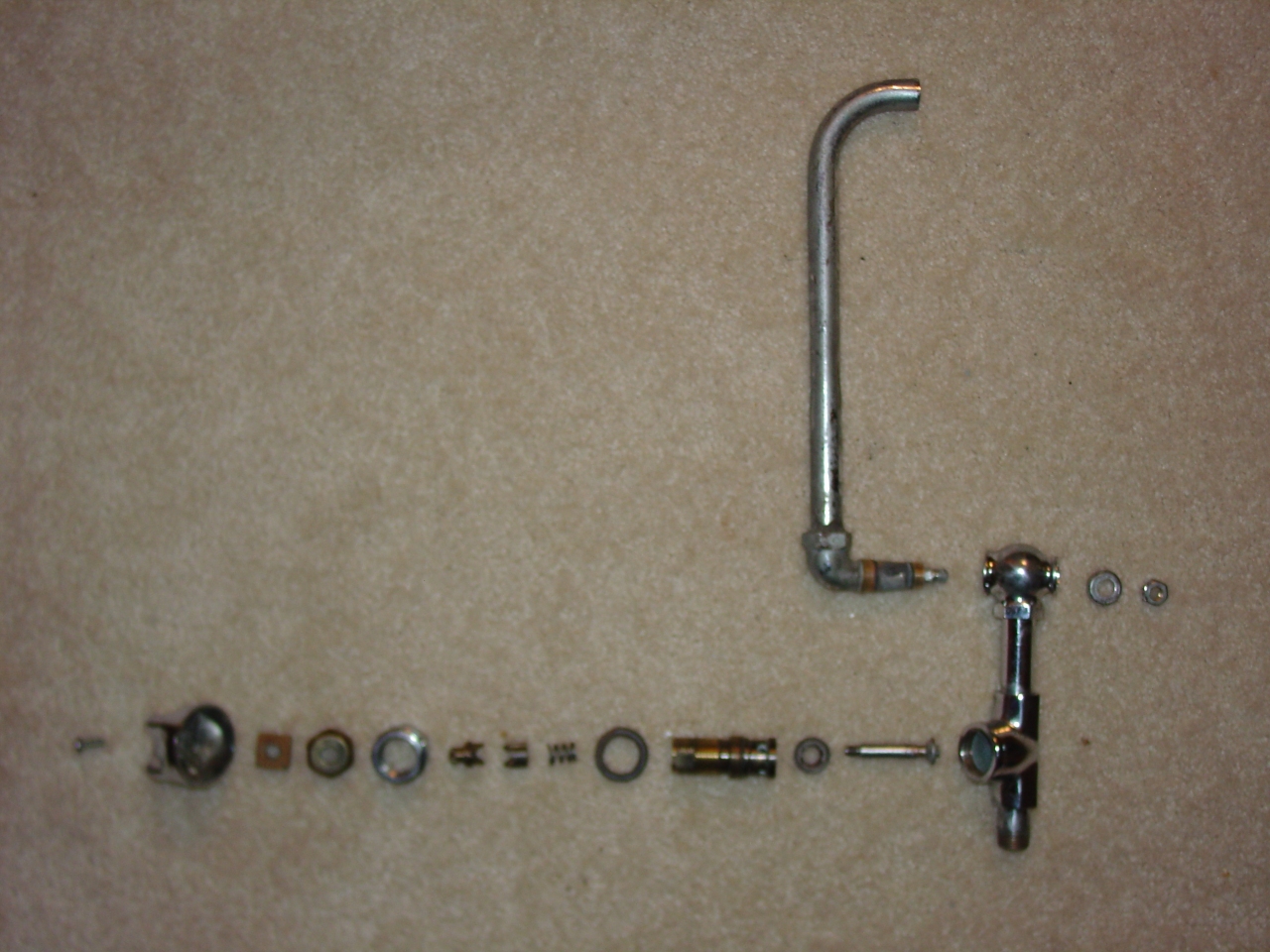
| This is an exploded view of the Adlake No. 138 faucet, with the new gaskets I found. That big red one needs to be trimmed to fit. The metal parts were polished on the wire wheel, then lime deposits removed by adjitating them in a bowl of Lime-Away. During reassembly I'll use Never-Sieze on the screw threads, and plumber's grease on moving parts inside. |
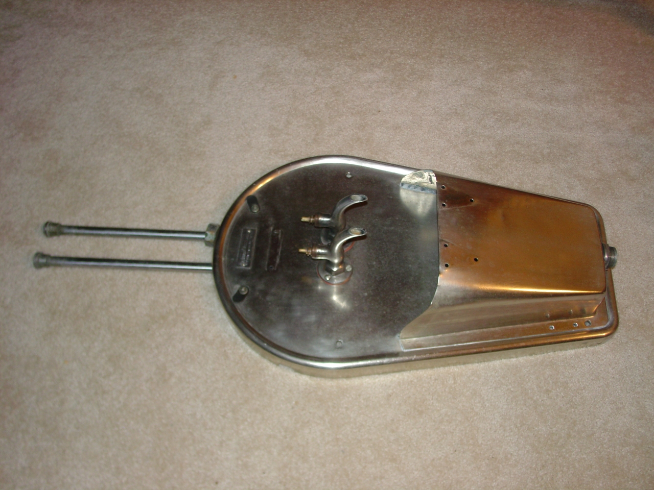
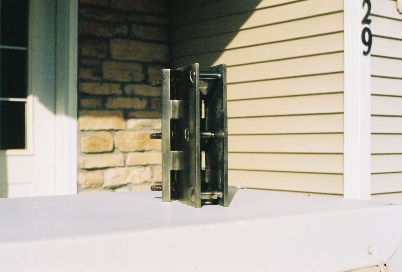
| Here's the back of the fold-down lavatory. These pipes are already drilled and tapped to be arranged for either top feed or bottom feed. The base is just cut to fit. The original openings are at right (bottom.) The new openings I cut with a drill and band saw at the museum shop. The pipes and faucets are both gasketed to the base - cut from 1/16" sheet rubber with an X-ACTO knife, and then holes made with gasket hole punches. |
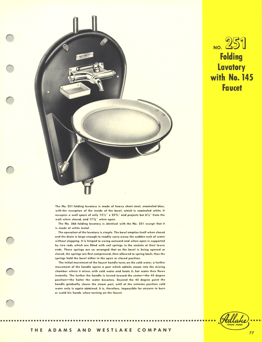
| This is the Adlake catalog page for the fold-down lavatory. |
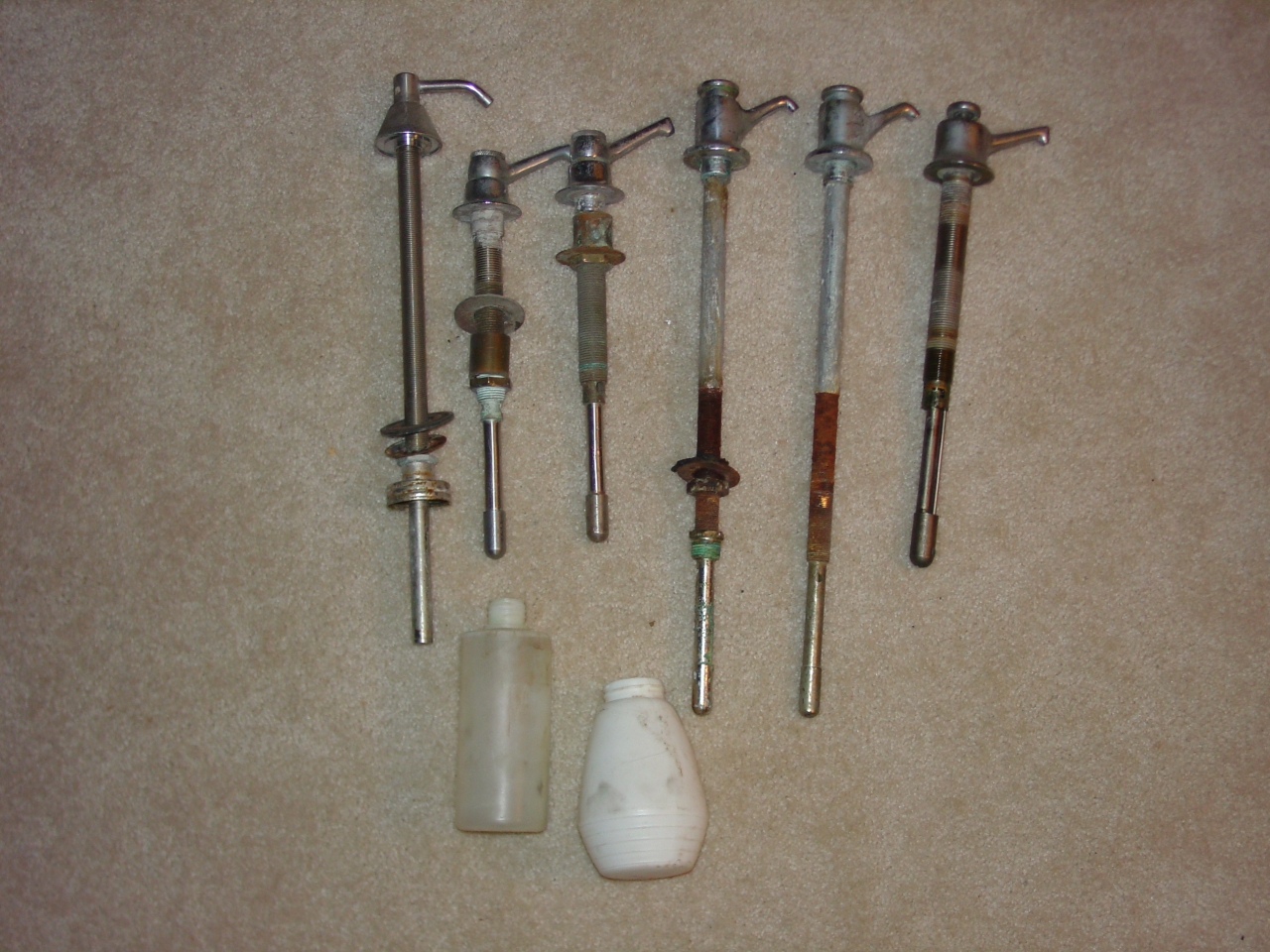
| Various and sundry restroom lavatory soft soap dispensers. The one at far right came from an ex-NP, ex-CNW 400 coach at Illinois Transit Assembly Corp. It's wet with penetrating oil near the bottom -- I'm trying to disassemble it to free up the pump mechanism. The rest just arrived from Dave Varilek. |
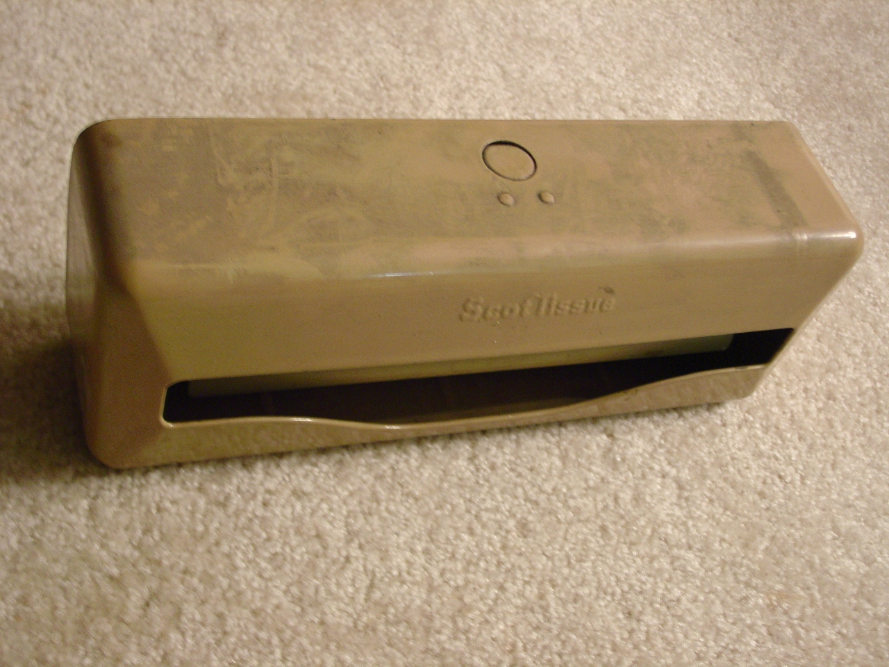
| This is a Scott folded paper towel dispenser. It holds fifty, and is correct for the kitchen, above the fold-down lavatory. It just arrived from Dave Varilek, and I haven't started in on it yet. I'm hoping its stainless or nickel-plated under the paint. |
I actually haven't done much work on 1146 this month, because I've been working on this web site. Thank you to everyone who's had nice things to say about it!
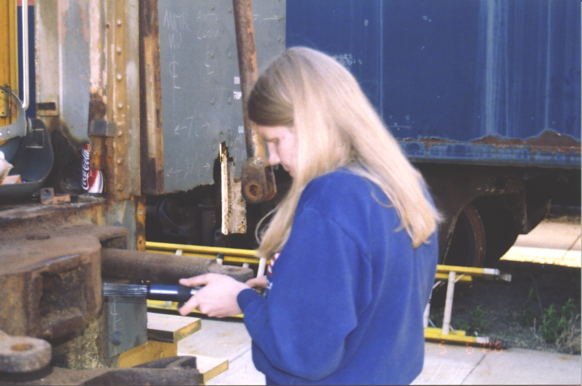
One piece of progress I can report is that the kitchen fold-down lavatory is nearly finished and ready for installation. I just need to adjust the spring-loaded push-rod length to level the bowl, and clean/assemble the S-trap. My girlfriend has been helping. (Ummm ... at least one evening we got into a long conversation and had to tell the sink to "assemble thy self" - it didn't listen.)
The Scott paper towel dispenser pictured above has been stripped of paint. It appears to be mild steel, so I'll either be painting it silver or buffing it well and painting with clearcoat.
My spring calendar is really filling up. I had been thinking of taking 1146 for a spring fling, but decided that by the time I got it organized, it would be too hot out and we'd only suffer inside. (No A/C system!) Therefore, on March 20th I submitted a bill of lading to the BNSF, to have it moved to the Minnesota Transportation Museum. I specified myself as the shipper, and the museum and the recipient.
There was an error in my bill of lading. I said it was a "load". Should have been an "empty". The BNSF computer types fixed it for me.
Monday the 3rd the St Croix Valley notified me that 1146 had been delivered to the BNSF in interchange. They turned it over to the local that operates out of Northtown yard in Minneapolis.
Monday and Tuesday after work I visually check the hump bypass track at Northtown. No 1146. A friend who used to hostle at Northtown speculates it might be in the transfer yard, at Midway yard, at Union yard, or even still on a Northtown receiver track. I'm starting to appreciate how easy it is to lose cars in a yard.
Wednesday morning someone from the museum called. He'd just gotten off the phone with local BNSF folks. They said they'd be delivering the car Friday morning. Yippeee!!! I'd already put in my request to park 1146 outside near the pole barn, for vehicle and shore power access. After talking to the superintendent, it will land on pole bard track 3, between the pole barn and the museum, where GN 1215 currently sits. Next I called the switch crew to give them a heads-up.
I've decided to take a week off work - May 6th to 14th - to have a "blitz" work session. (Except Saturdays I really out to work on MTM stuff.) My main goals are vestibule steel work and installing the 480-208 step-down transformers. I'll welcome anyone who wants to help. Here is my agenda - as a Microsoft Word document or an Adobe Acrobat pdf file.
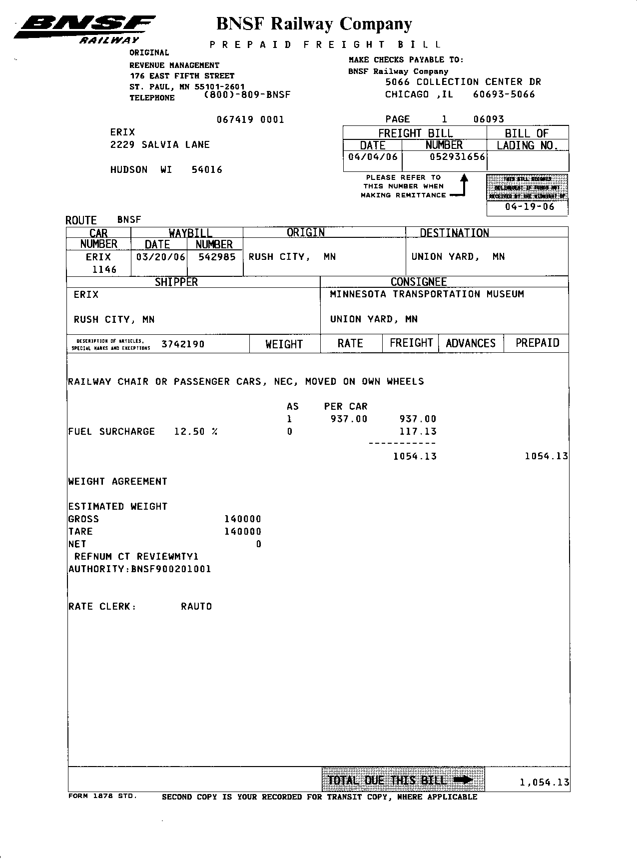 | If anyone is curious, here's what the bill for the move looked like. |
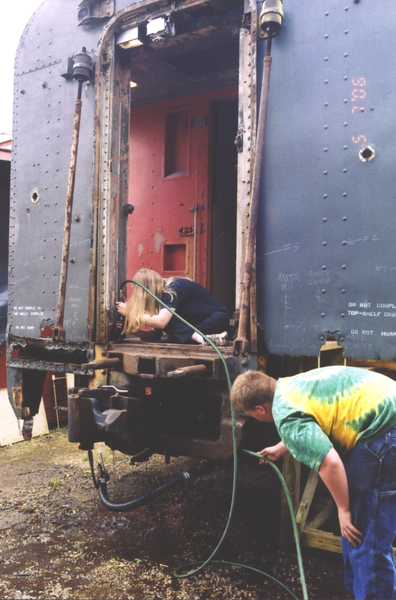
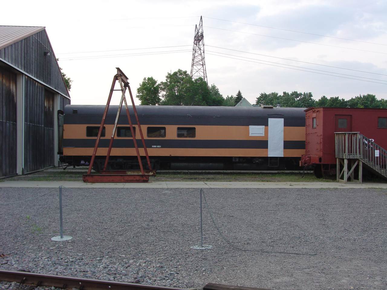
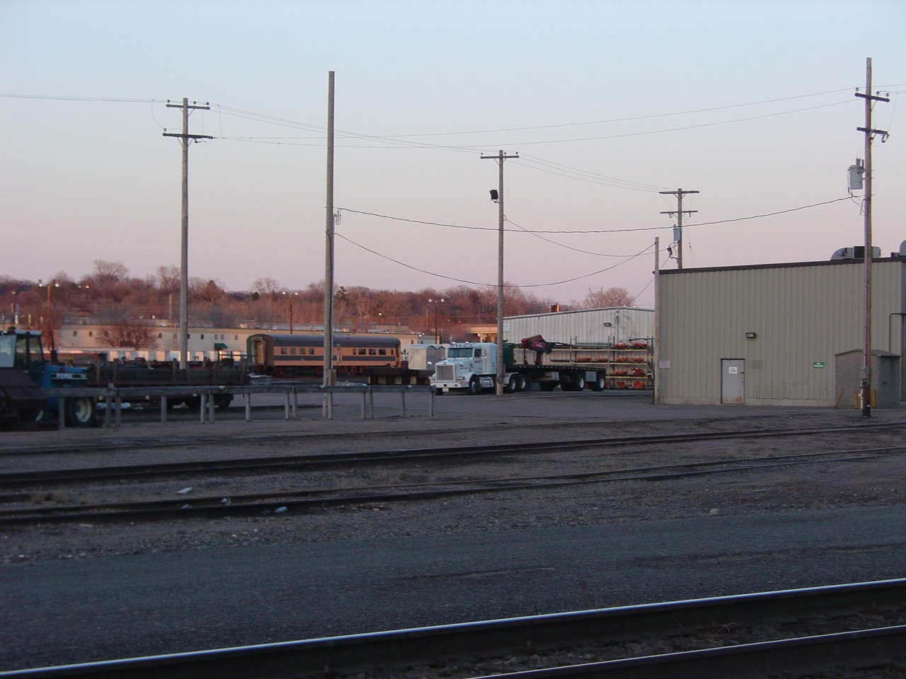 | Friday evening after work I checked at the museum - it hadn't arrived yet. So I went hunting, and found it in Union Yard at sunset. It was moving when I spotted it. The local switch crew had it tacked on behind their caboose. (The "tramp", as a former hostler friend calls it, uses a caboose because they do so many long-distance backup moves. It's more comfortable for the crew than hanging off the side of a hopper car.) In this picture, they've dropped it while switching industries near the stone arch bridge. Neat stuff: The foreground track was once the double-track passenger main from St Paul to Minneapolis via the stone arch bridge. Amtrak used it until 1979. 1146 would have been a regular through here in the 1960's. The shop building on the right is "Bridal Veil". Currently used for materials, it has also been a freight car shop and was once the maintenance base for the BN business car fleet. |
 | The BNSF switch crew delivered 1146 Saturday evening. In this picture I've just checked it over and found all was well. We told them "just park it here - we'll put it away." |
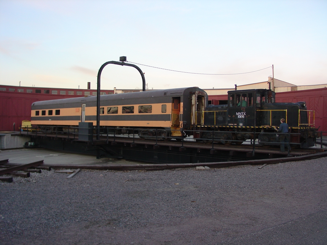 | Using the turntable as a run-around. |
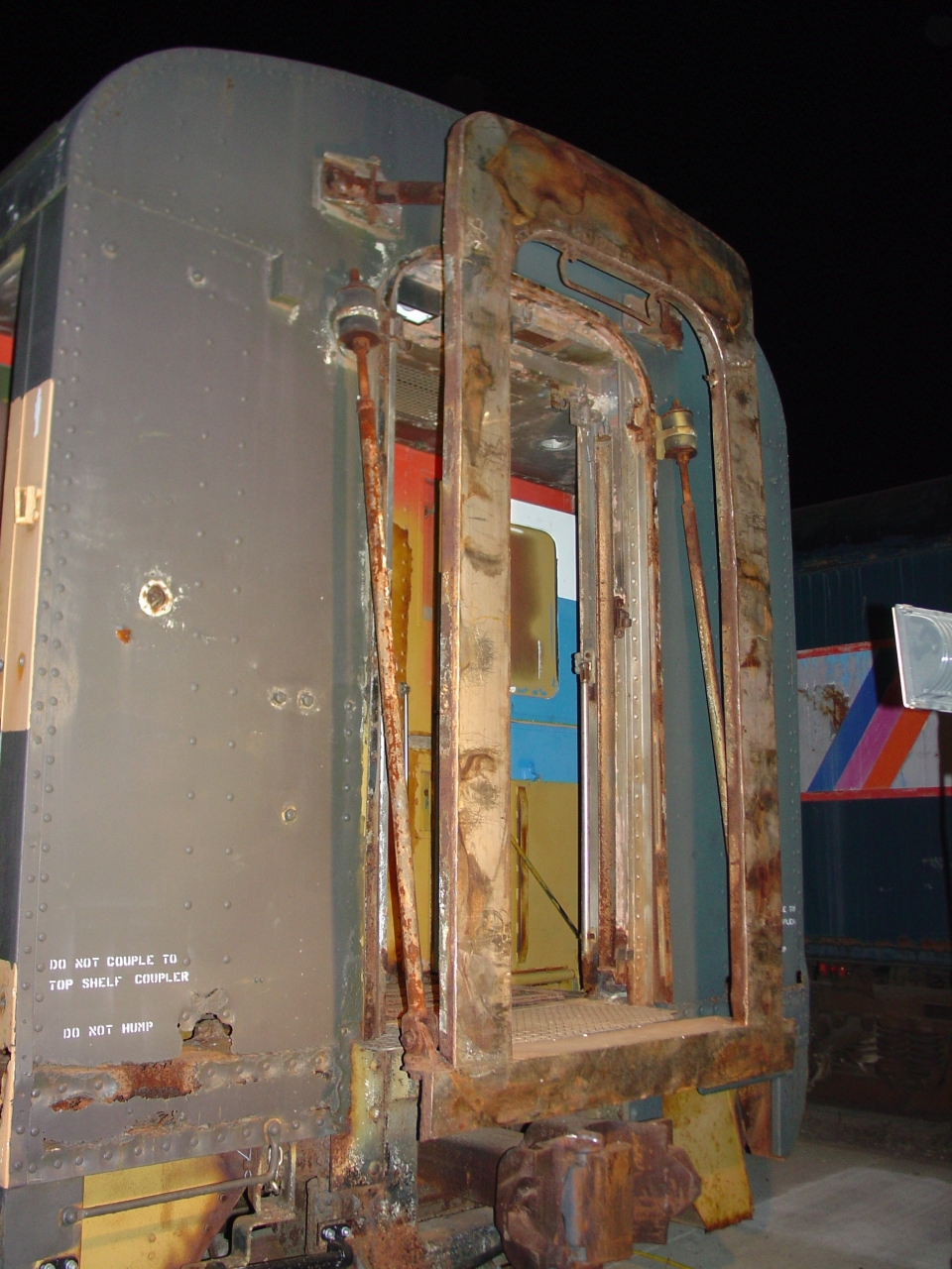
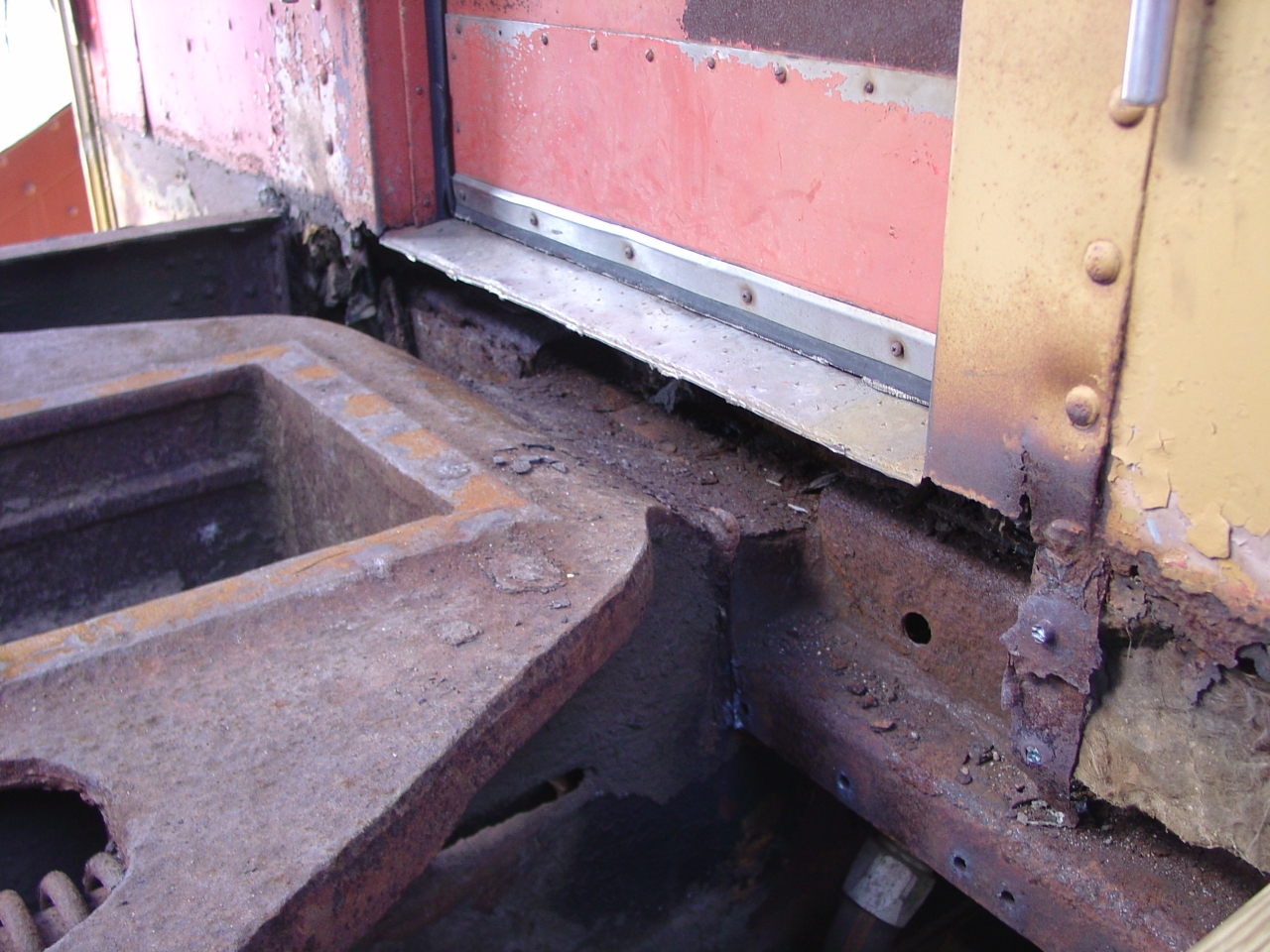
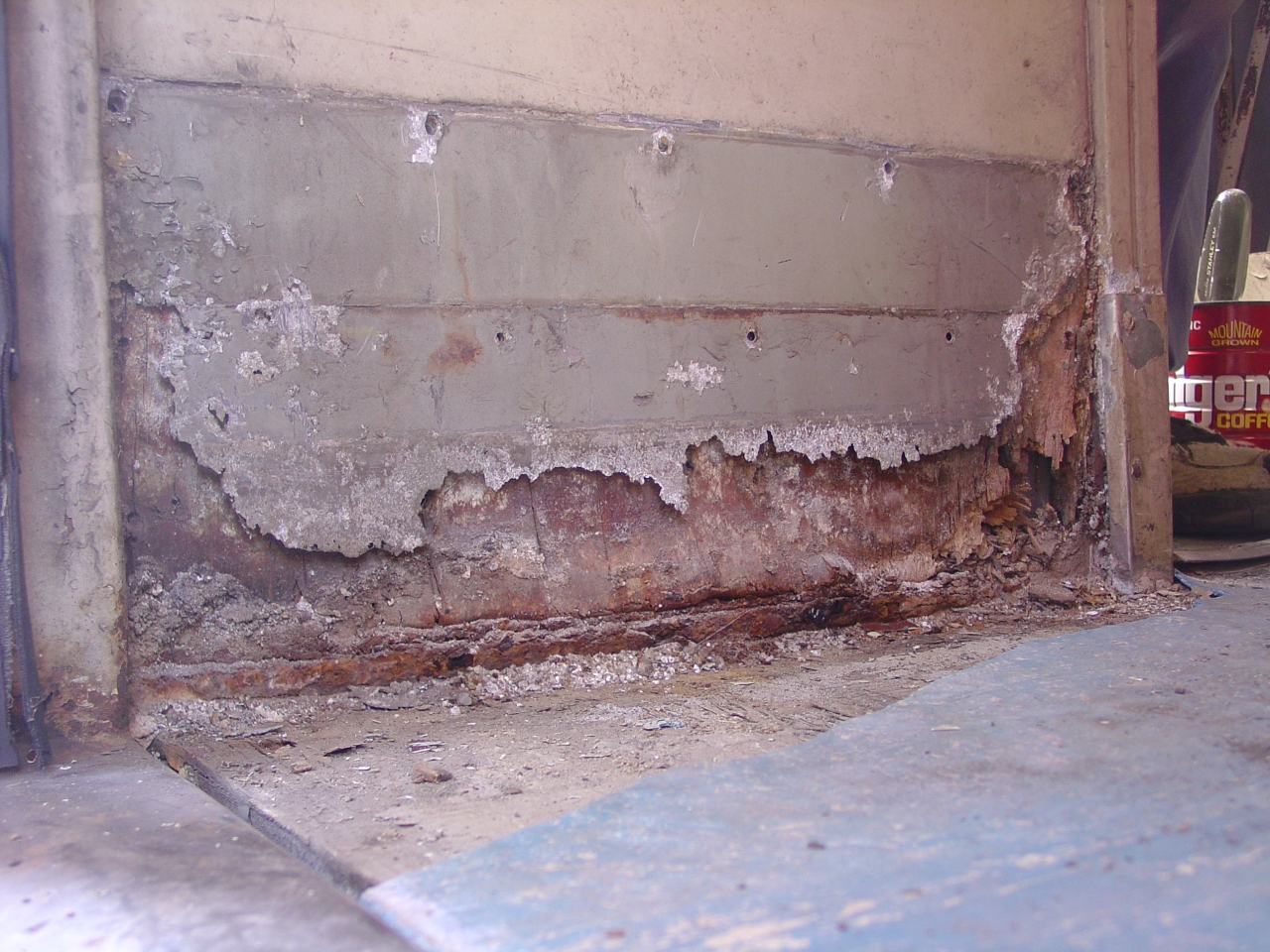
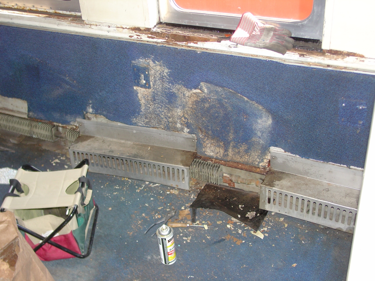
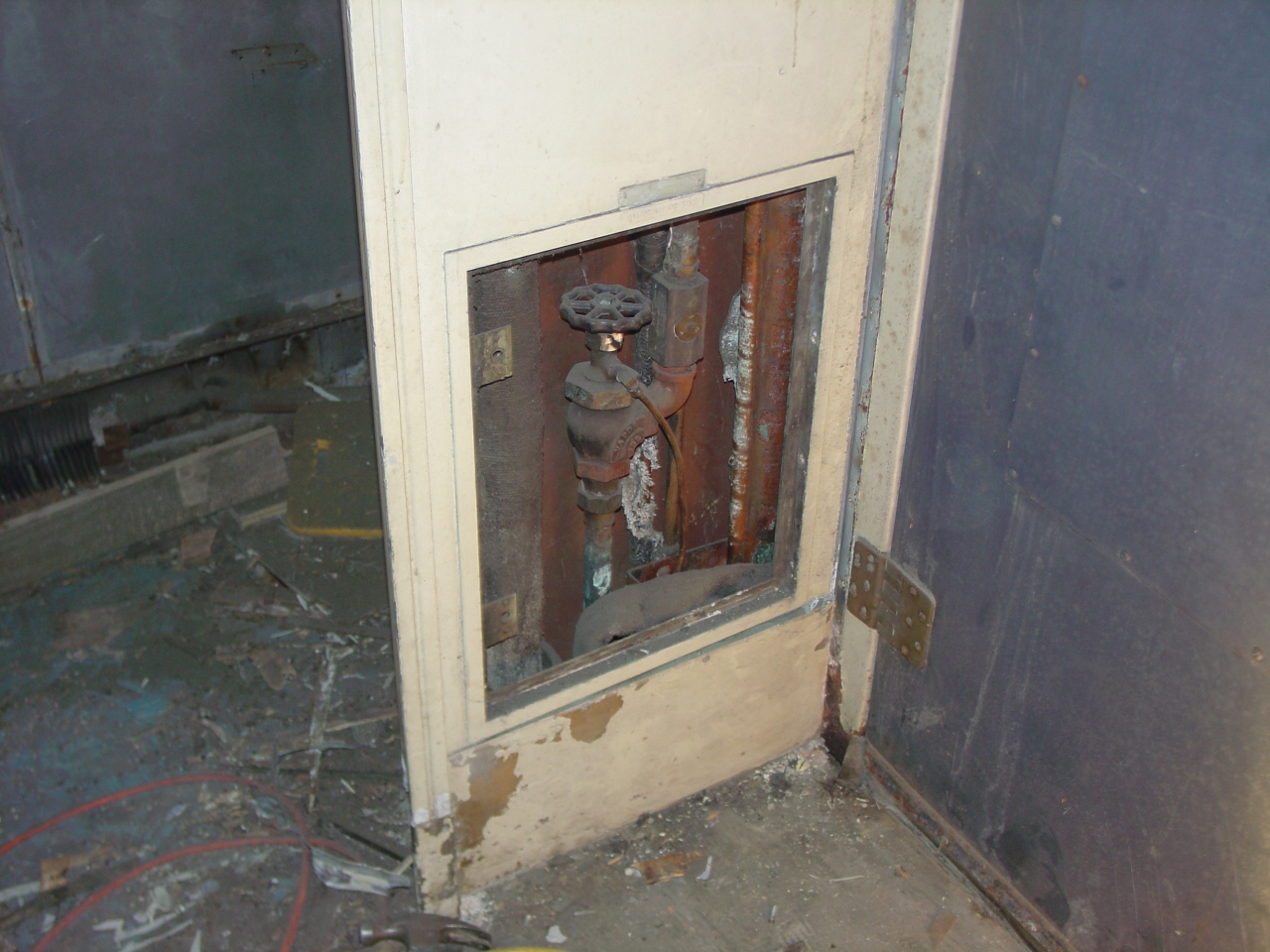
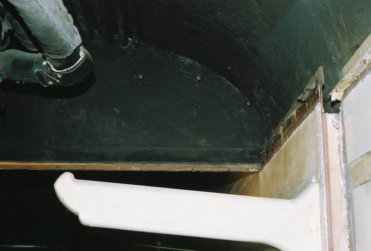
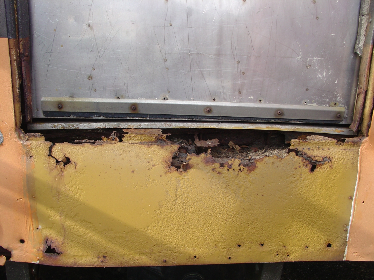 | I've still been having problems with a wet/mildew odor. My latest theory is that water is running down the kitchen commisary door, and in through the rotted sill. (Funny it took me five years to figure this out.) In this picture I've just removed the stainless kick plate. |
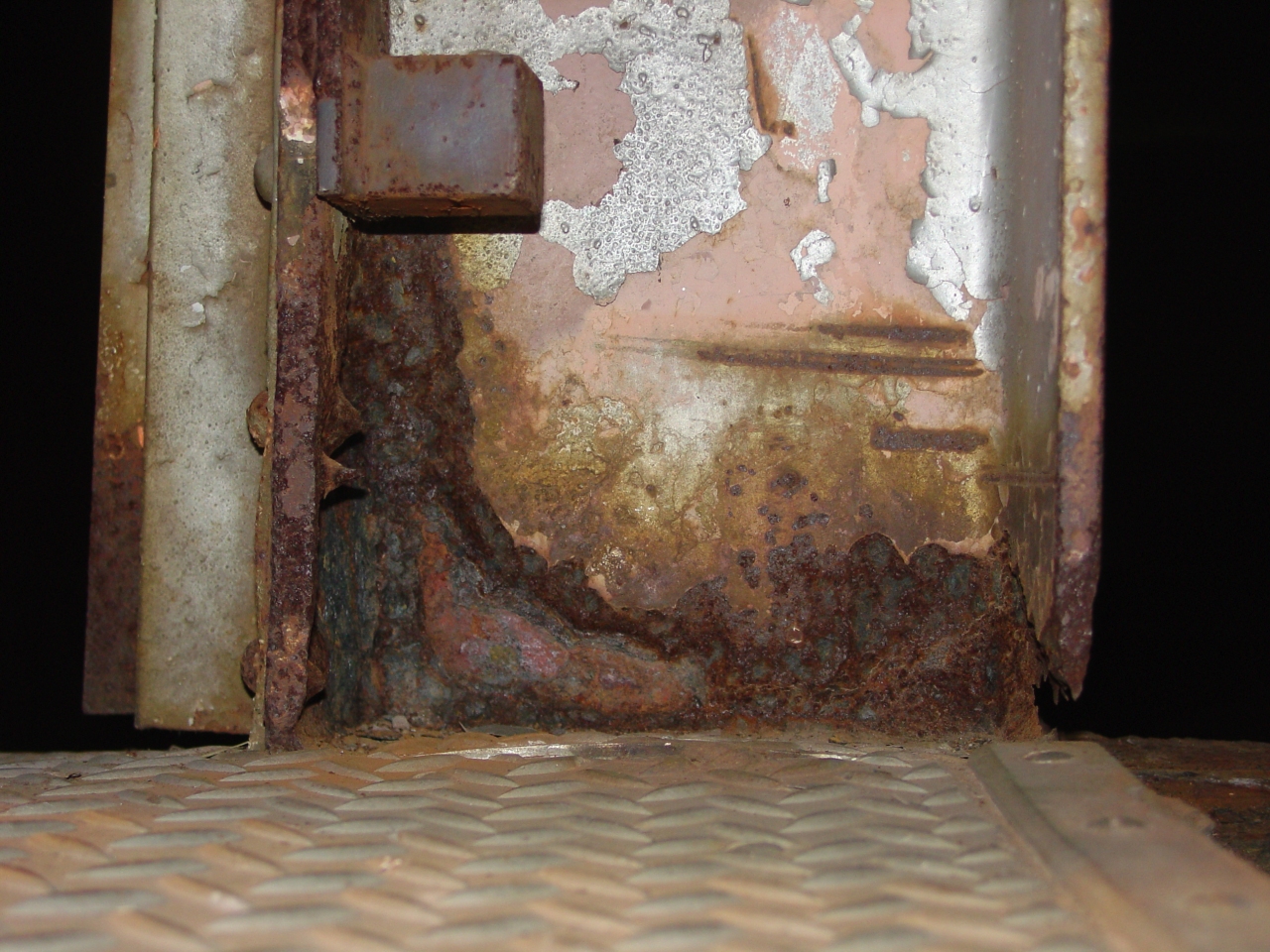
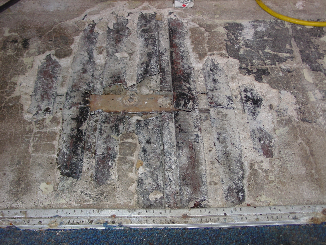
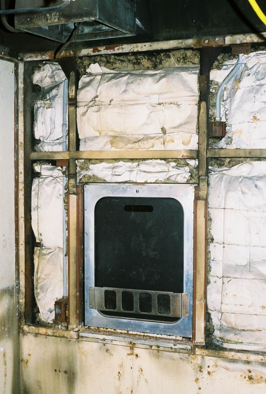
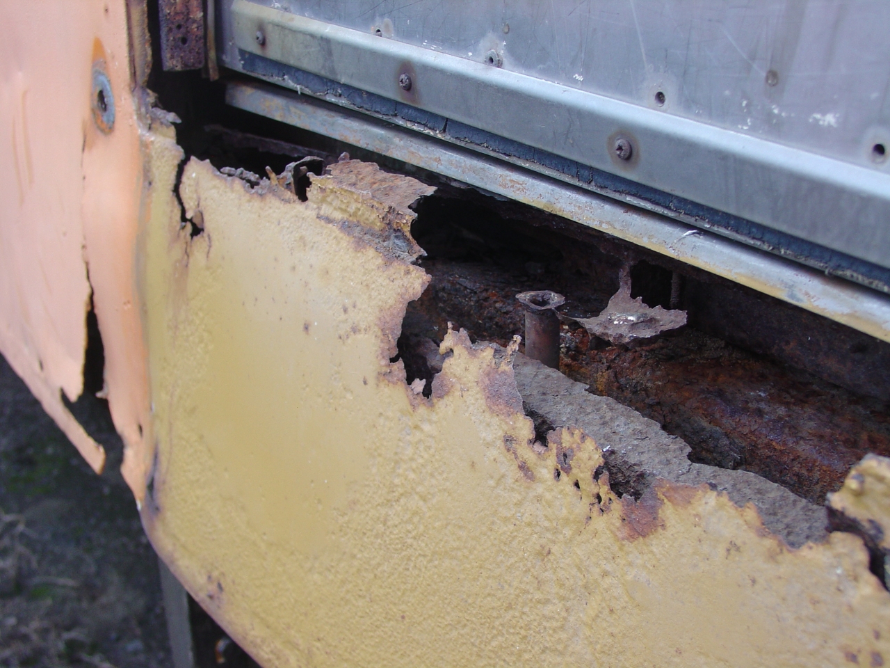 | The opening was full of rust chunks and white sand. I vacumed out as much as possible to allow things to dry out more quickly. That pipe is all that's left of a water catch basin under the sill. |
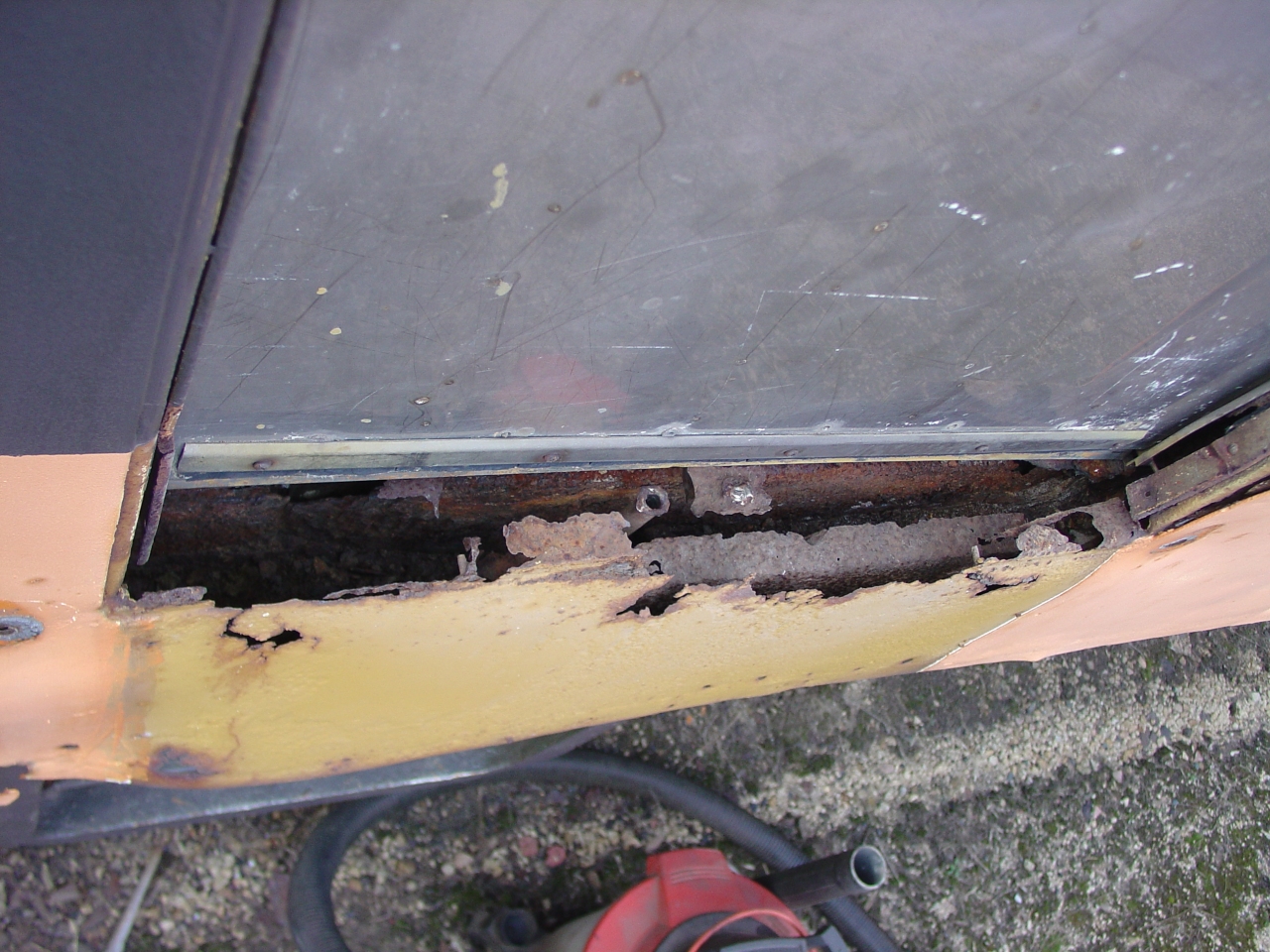 | Another view. The door is an Amtrak stainless steel replacement. |
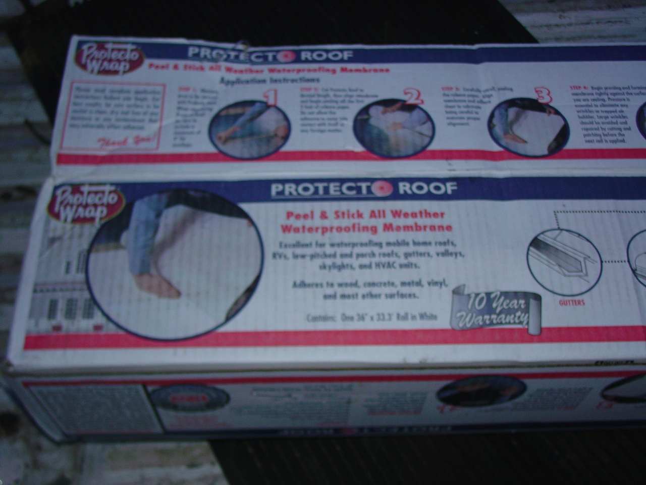 | This is some roofing stuff I found at Menards. It's like a rubber membrane with an adhesive backing - like giant Scotch Tape. We'll see how well it works. |
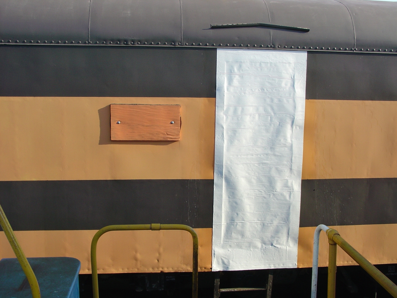 | I removed the grab irons (carefully labelled and tucked away,) washed the paint with TSP, ground off any bumps from broken screws, and when it was dry put the membrane up. The top edge is tucked under the roof lip. |
At the January RPCA conference, I took some "Installing HEP" courses and got a copy of the Amtrak private car manual. They taught me I'd been using the wrong crimp tool and connectors for the wiring. I'd been using a pliars-type multi-purpose electrical tool to crimp connectors from Home Depot. Amtrak requires a ratchet-type crimp tool with a die, because it provides more consistent crimps, and it must crimp both the ferrule on the conductor and the sleeve on the insulation. Their approved parts number list is dated, but works out to be the Pre-Insulated Diamond Grip ("PIDG") line from AMP. (AMP is now part of Tyco Electronics.) I decided to buy a kit, reckoning that would be a job for someone during my work week.
AMP's PIDG line is very extensive. I went for ring terminals only (spade and hooks are prohibited by Amtrak, and I've no immediate need for fast-on's.) They are sized by wire size, insulation size, stud size, length, and width. The items I ordered from Newark for my kit were:
Note: I sized for a larger wire insulation diameter, since I'm using Exane with the thicker 2kv jacket. I ordered from AMP catalog 82042, revised 8-00. Other suppliers were supposed to be cheaper, but Newark had everything in stock.
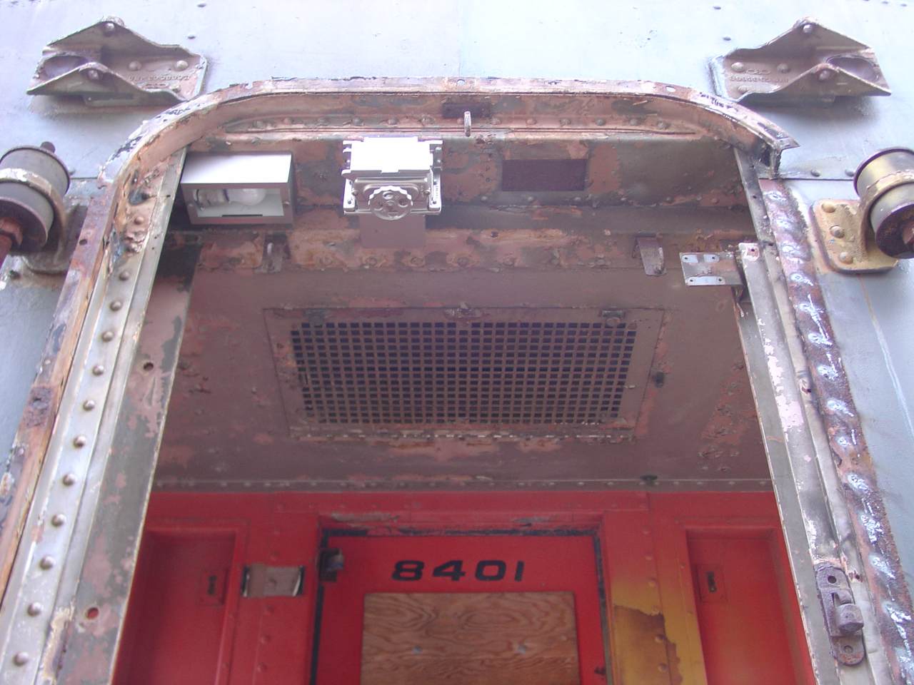
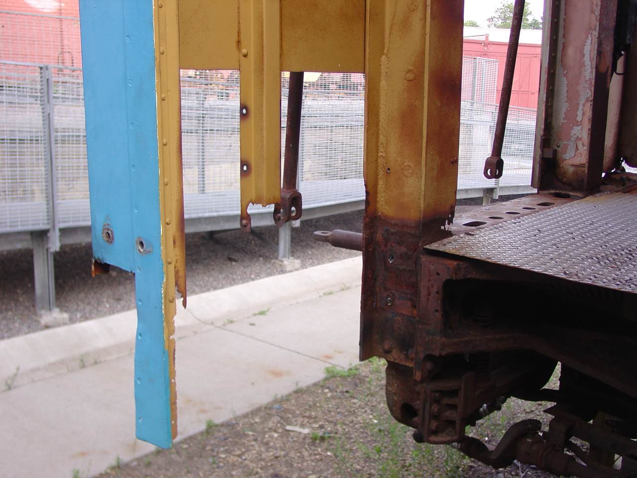
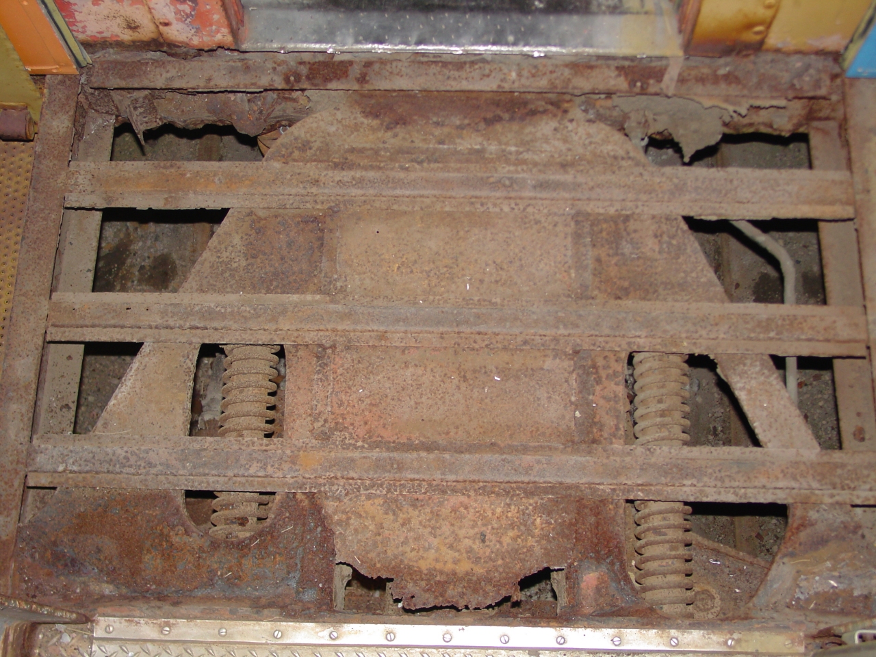 | To assemble a steel order, it seemed smart to do a little exploratory surgery. Here we're looking down at the vestibule platform, after the stainless floor and mostly-rust subfloor were pulled up. The camera is in the diaphragm, and that's the door into the car at top. The vestibule floor structure is built around the big, structural end casting. That casting carries the drawbar and is strong enough to resist jack-knifing in a derailment. It also carries the buffer springs and anchors the collision posts. |
 | Here's a study of the diaphragm, after the canvas was removed. The buffer plate (floor) is spring loaded to maintain constant contact with the next car. The diagonal braces are just for support. The horse-shoe (top and sides) are kept tight against the next car by the leaf spring at the top. The leaf spring ends float on a captive steel ball. For Amtrak service, the horse-shoe is torched off and replaced by rubber tubes. I like the older look better, and plan to repair the existing steel. |
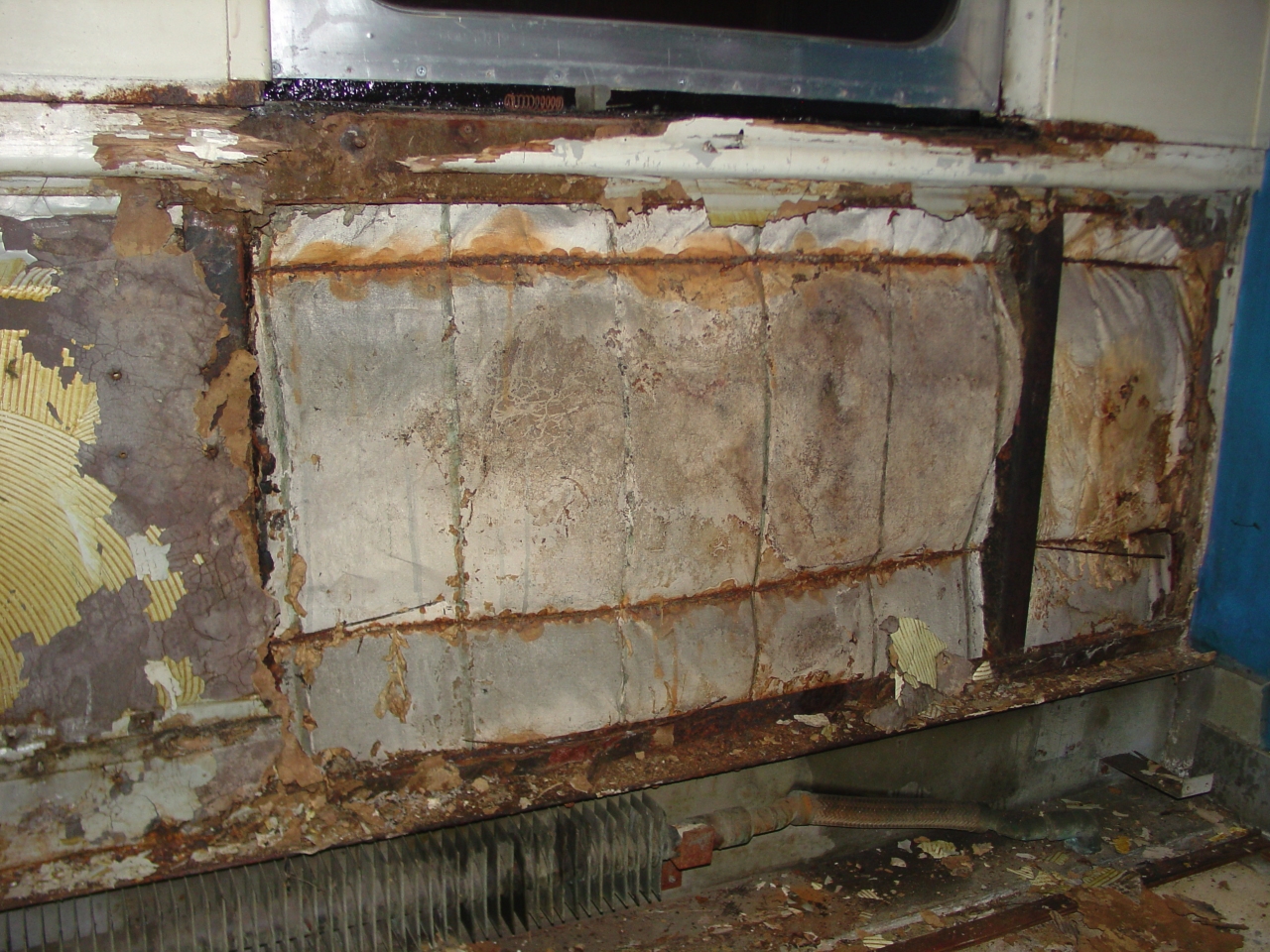
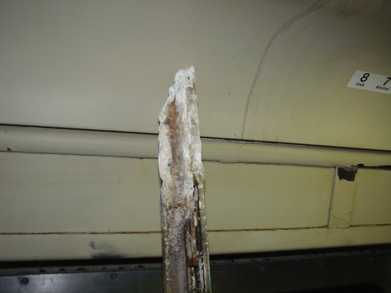
 | This illustrates why I reckon the collision posts need help. They are intended to absorb the energy of a collision, to prevent one car from "telescoping" inside another. However, at floor level they've rusted to 25% of original thickness or less. Salt used to remove snow is usually blamed for this damage, but this area is prone to trapping moisture as well. |
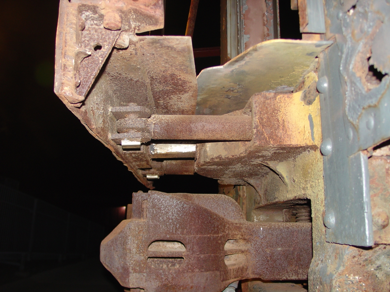 | This nicely shows the relationship of the end casting, coupler, buffer plate, walkway, and collision post to each other. Notice the coupler rides on a spring-loaded carrier, the floor is notched to allow the buffer plate to move, and the collision post is riveted to to the end casting with about twelve 3/4 inch rivets. |
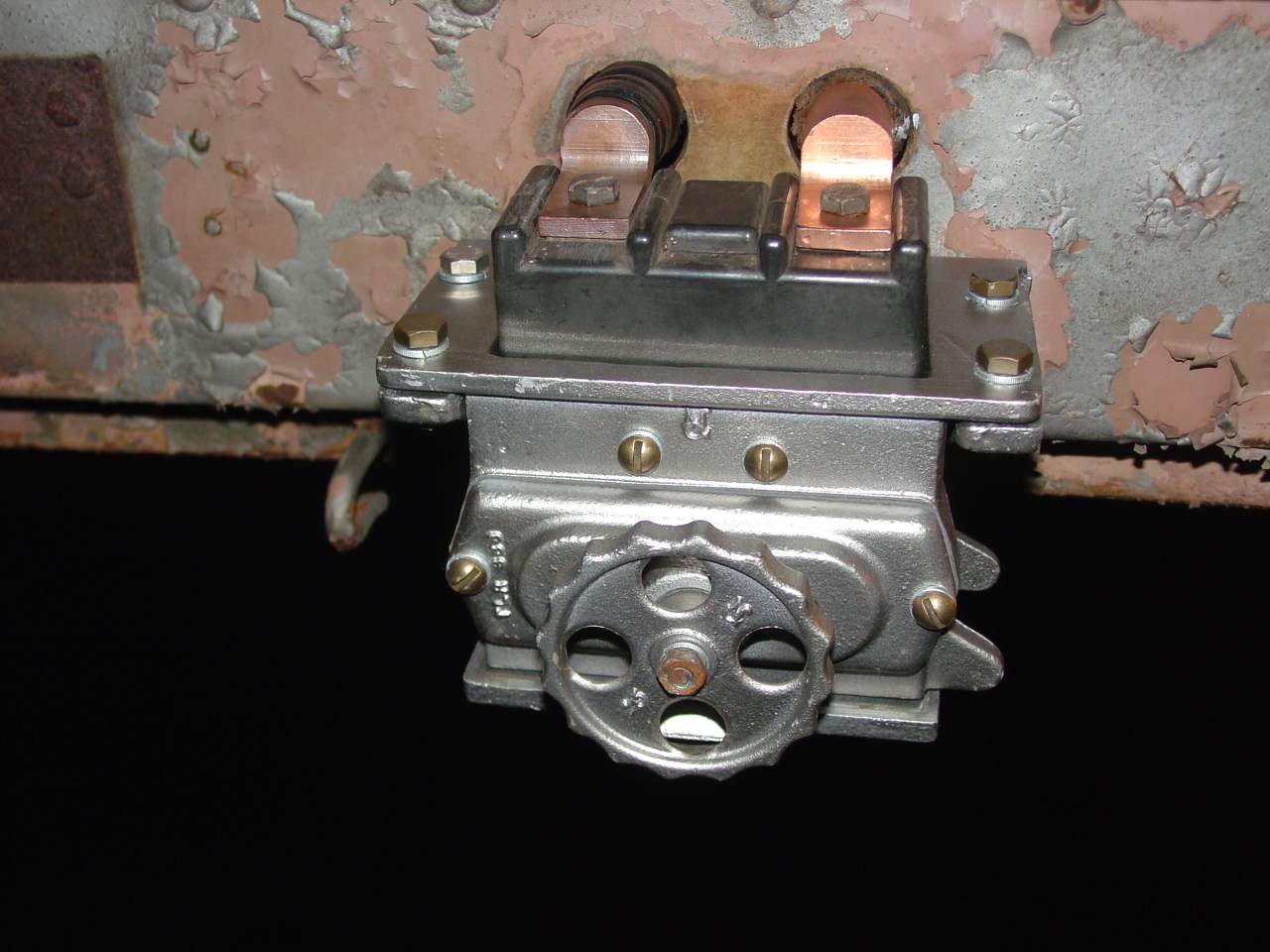
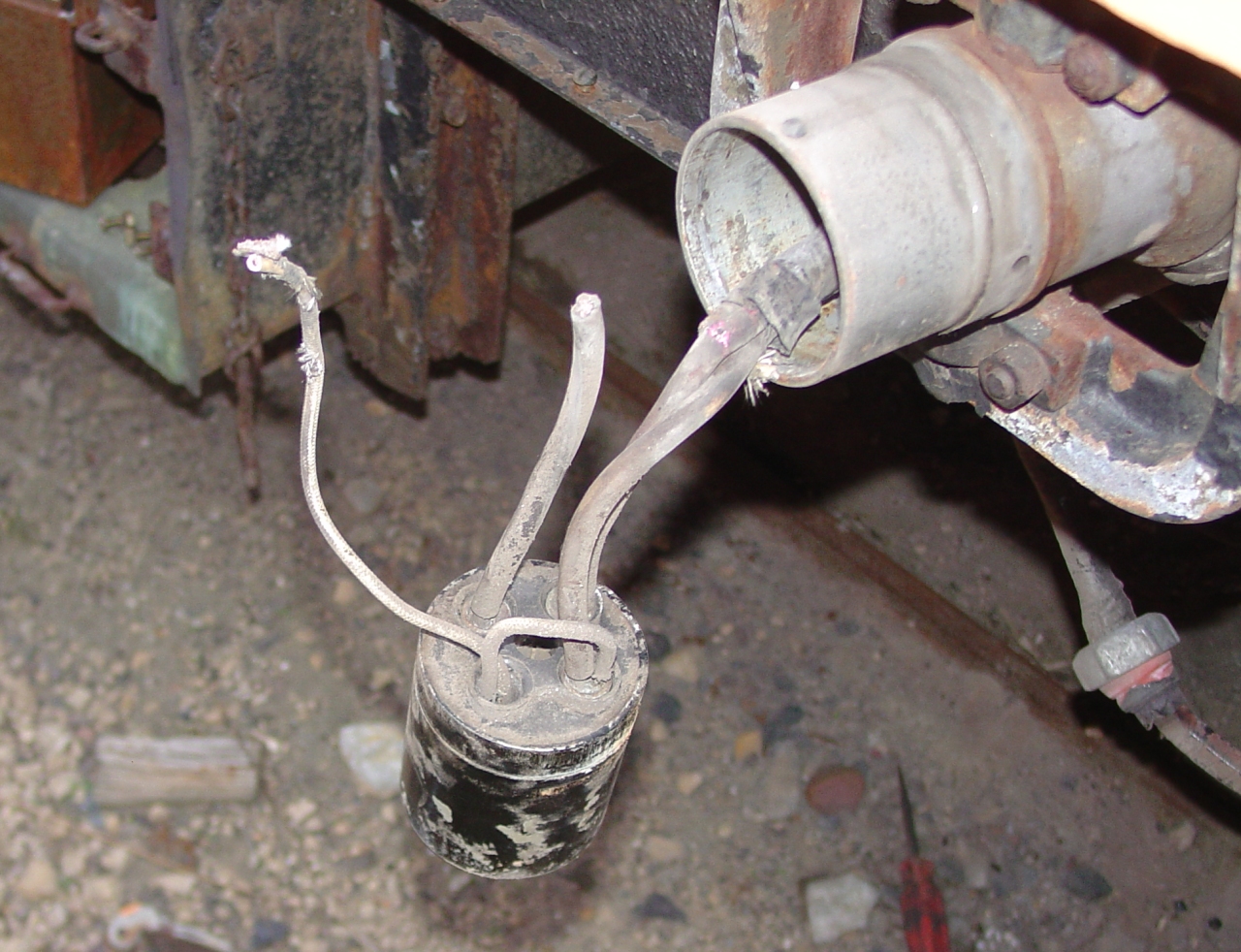 | The museum has 208-Y three-phase available, same as 1146's lighting sub-panel uses, so I temporarily modified the shore-power connectors. As seen here, shore power was typically a 60-amp Pyle-National Quelarc connector with three long pins for 208 delta three phase, and a short split pin to pilot a contactor in the car. When inserted, the power pins would connect first, then an unconnected line in the plug would short the split pin, picking the contactor and connecting the load. This scheme prevented unnecessary arcing damage. I modified the fourth pin to be the neutral wire needed by 208-Y. I also grounded the carbody to the rail, to protect the journal bearings from pitting. |
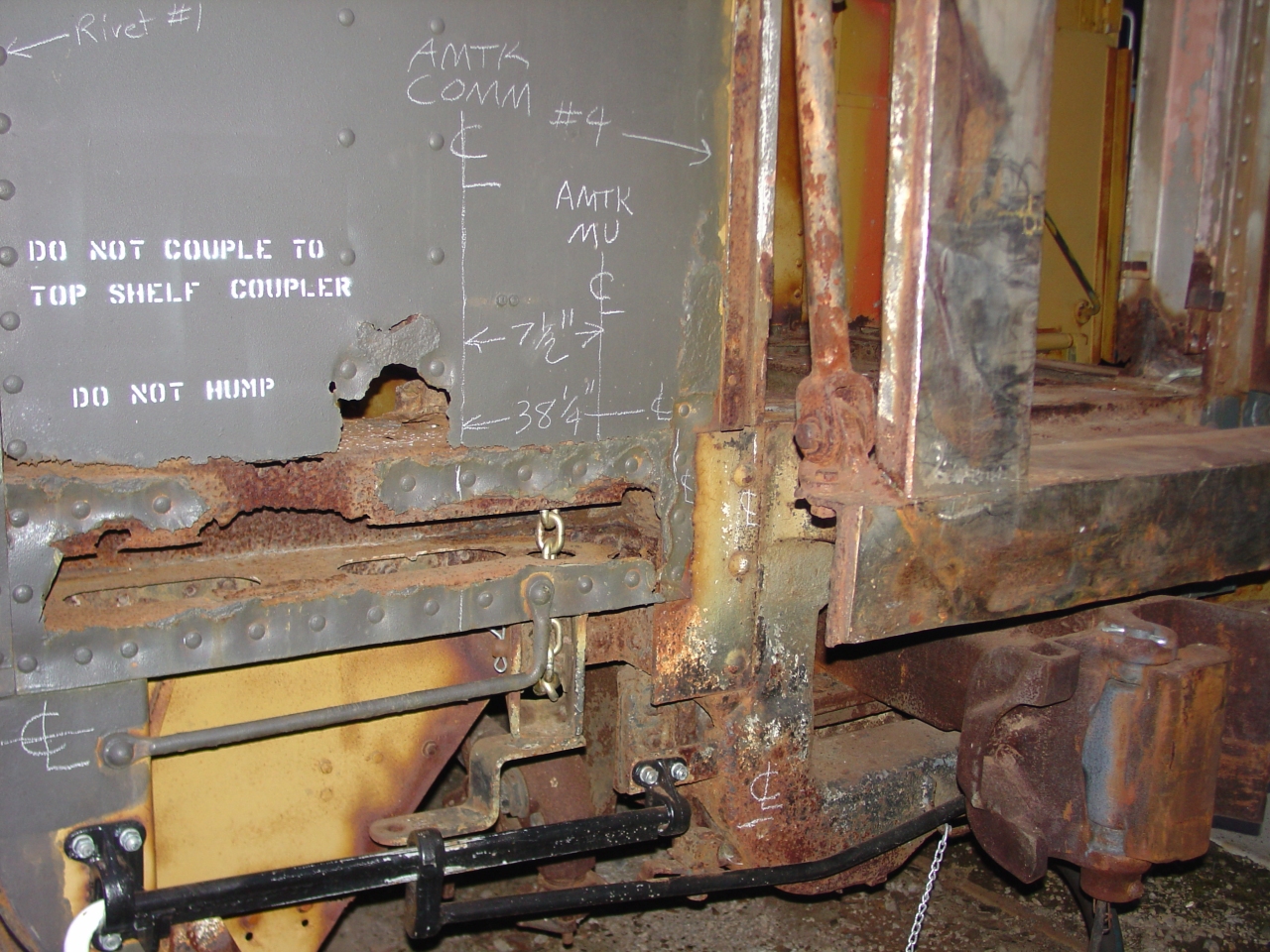 | Before deconstructing the vestibule, I marked out the required locations of the Amtrak trainline connectors. (Without including any permitted fudge factors.) The grab iron, hand brake chain, and uncoupling lever will all need some adjustment to provide adequate clearance. Interesting trivia: Amtrak specifies the heights relative to the floor height. The ACF construction drawings specify the floor as being 4' 3" above top of rail. |
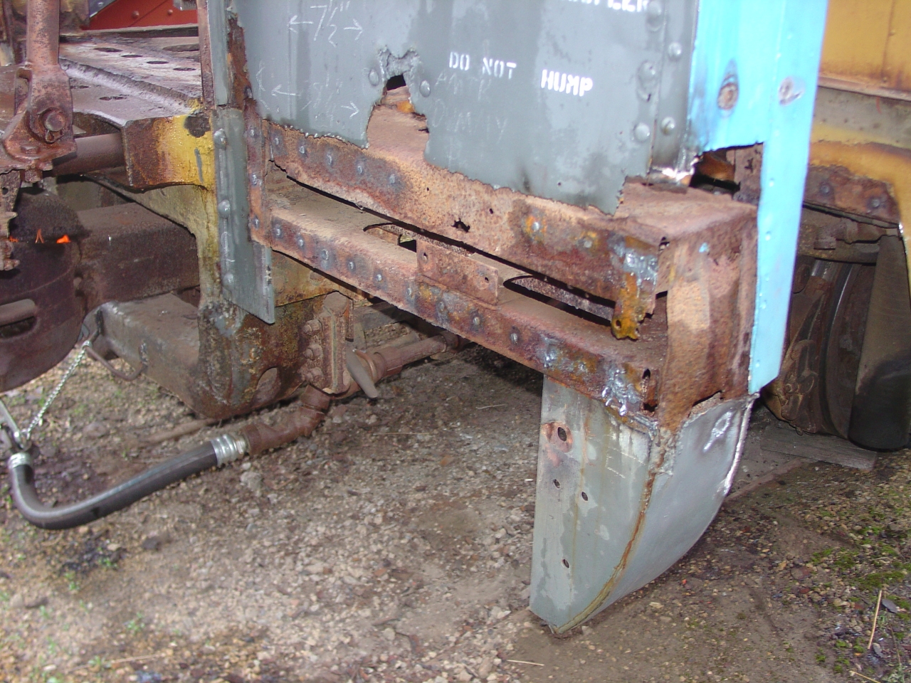 | The vestibule end wall structure, partly deconstructed. Two 3/16" low-alloy, high-tensile (L.A.H.T.) steel boxes were riveted to the collision post and end casting. They form the foundation for the steps, skirt, and end sheet. The skirt here was two angles, bent to the correct profile. The corner is .090" l.a.h.t. sheet bent into a box, with a .060" inside cover and 1/2" tap plates for grab irons. The end sheets and stiffeners are also .090" l.a.h.t. ACF used an aluminum extrusion for the vestibule door frame - gotta make sure I don't damage that! That bit of angle was where the full-width diaphragm spring was mounted. Factoid: Heavyweight steel cars were built of regular carbon steel. Light-weight streamlined cars used high tensile strength materials - but less of them - to achieve a weight reduction of 15 to 20 tons. Aluminum, stainless, and l.a.h.t. steel were all used. A USS product, Cor-Ten, was a common choice for l.a.h.t. steel. It is a copper-bearing speciality alloy designed for use in bridges and other unpainted applications. |
I spent hours looking at the original blueprints and bill of materials ("BOM",) just trying to find specifications for the vestibule materials that need replacement. One day something clicked: On the blueprints, I kept seeing numbers like 'VE-32393' or 'U-32089A', with arrows to particular pieces of structural steel. In the "Structural Steel Pieces" section of the BOM, there were similar numbers. But they were grouped by material type, making a cross-reference from the blueprint to the BOM difficult. So, I spent an evening at a coffee shop keying BOM data into an Excel spreadsheet for a cross-reference. Viola! From that I built a steel shopping list, using original material specs and dimensions. ACF used a code in the numbers: The number part is just a unique number. The prefix loosely identifies where in the car. 'VE' being 'Vestibule End', 'U' being 'Underframe'. Those two made sense. Others, like 'IF' for 'Roof' did not. If multiple similar pieces were used, they got the same number but had a unique letter suffix. There were several like 'S-Shear #10' which I haven't deciphered yet.
May was upon me all too quickly. I still hadn't gotten my steel order put together - not to mention my rivet order. But that was seeming less important because it looked more and more like my work week would be spent disassembling the restrooms and coach section.
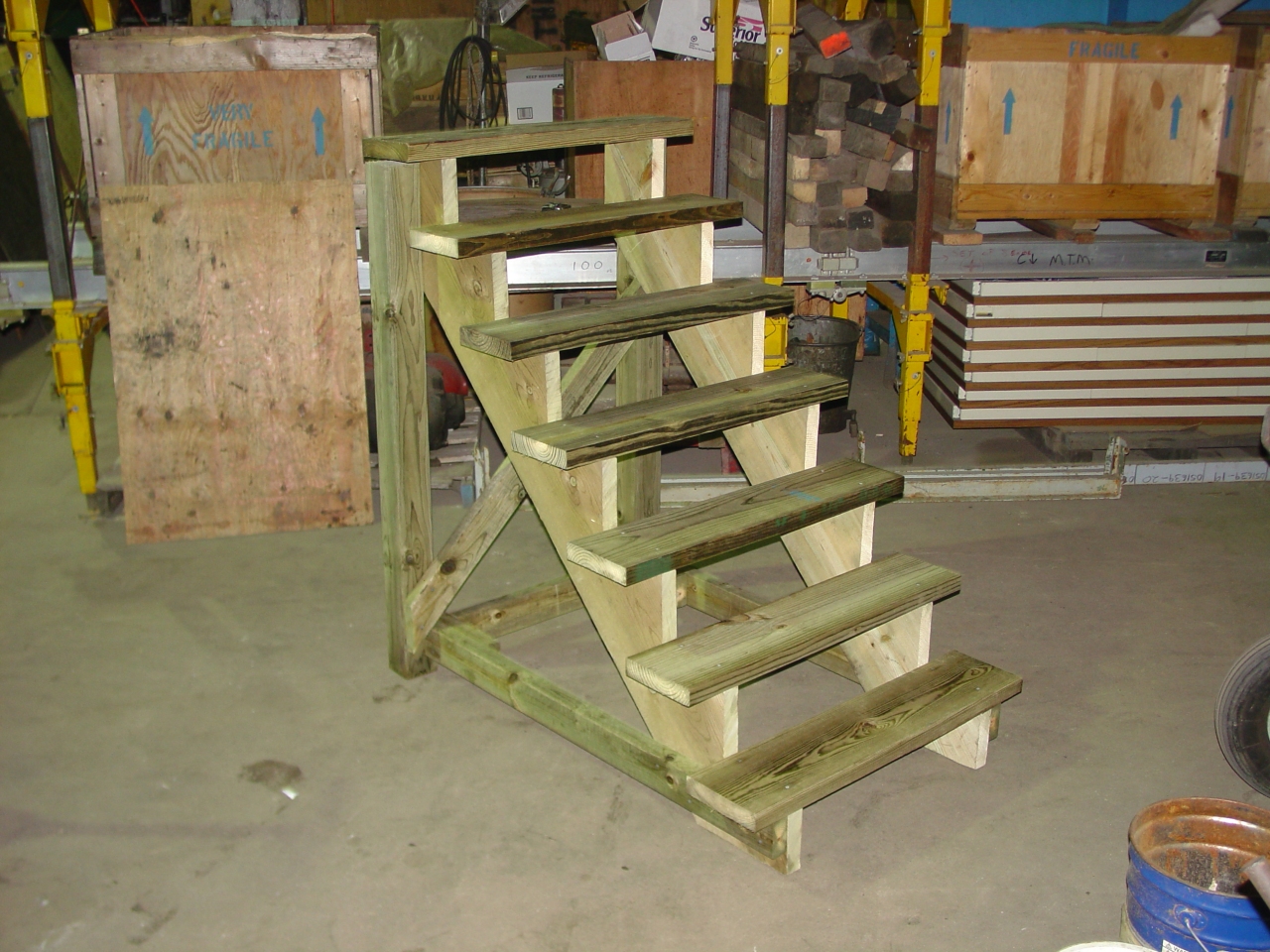 | I built these wooden steps to allow access to the car. At 33" wide and 4' 3" tall, they nearly exactly replace the car's own vestibule steps. I kept the rise/run ratio pretty steep, (roughly 7":7",) so they wouldn't stick out too far. The bottom boards have some ground clearance so they can be moved with a fork lift. Two people can also move them easily. |
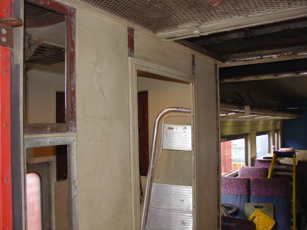
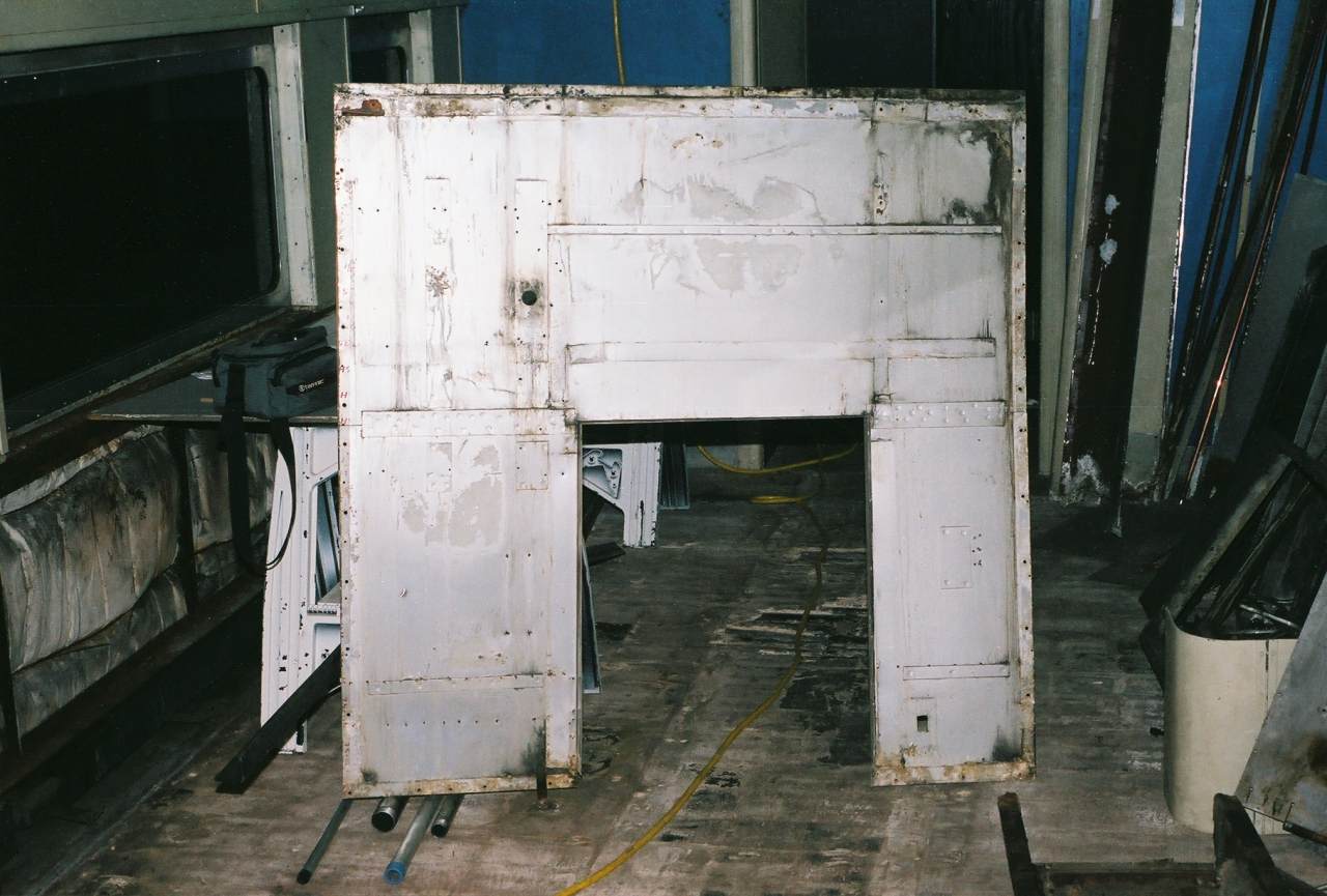
 | Here's where it went south. I'd planned to limit my current project to rebuilding the vestibule area. But ... the door threshold, the bottom of the door frame, and the car end where the platform and steps attach were bad enough to require repair. So, I started contemplating what that repair would require. Pretty soon I was looking closely at floor and walls of the restrooms just inside. |
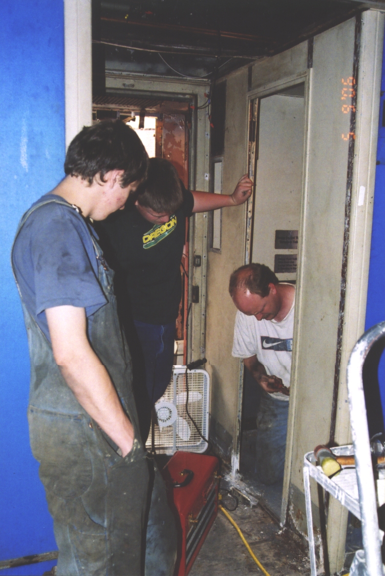
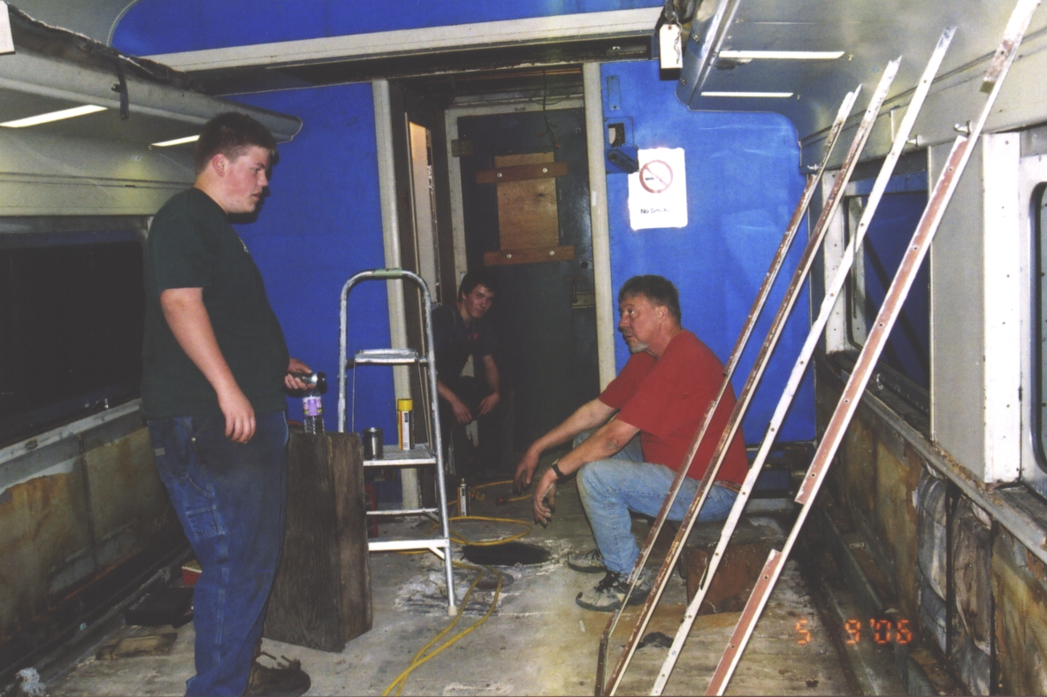
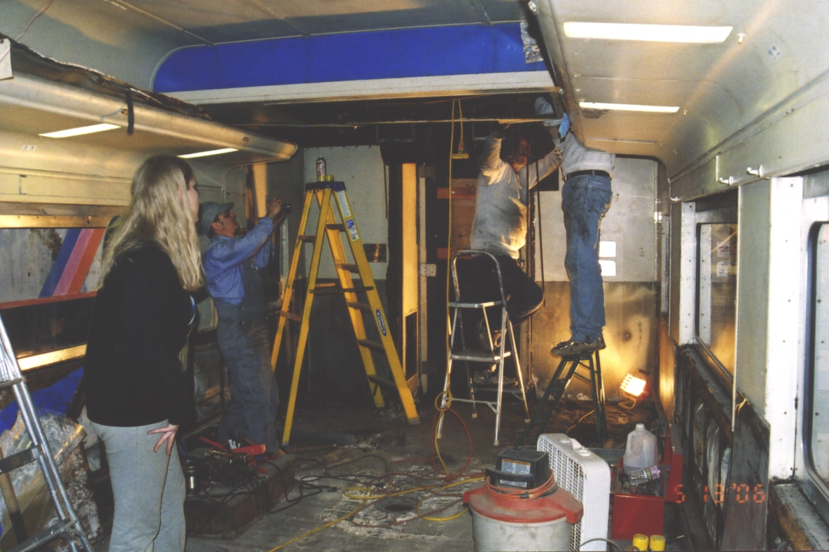
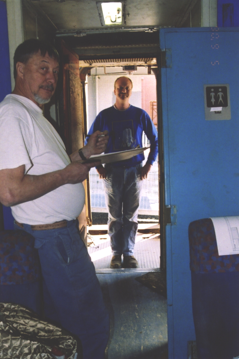 | Dad and I taking notes before starting restroom disassembly. |
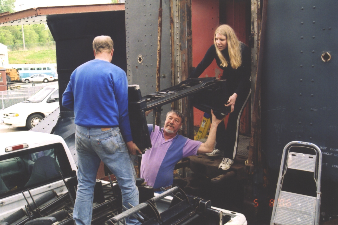
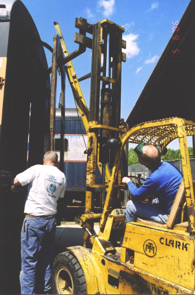 | While there was help around, I wanted to take the diaphragm and buffer plate off. The forklift steadied things while we unpinned it. The weird forklift angle was due to available space, but made it rather awkward. |
 | All the bolts were rusted solid. It proved fastest to cut the bolts capturing the top spring. |
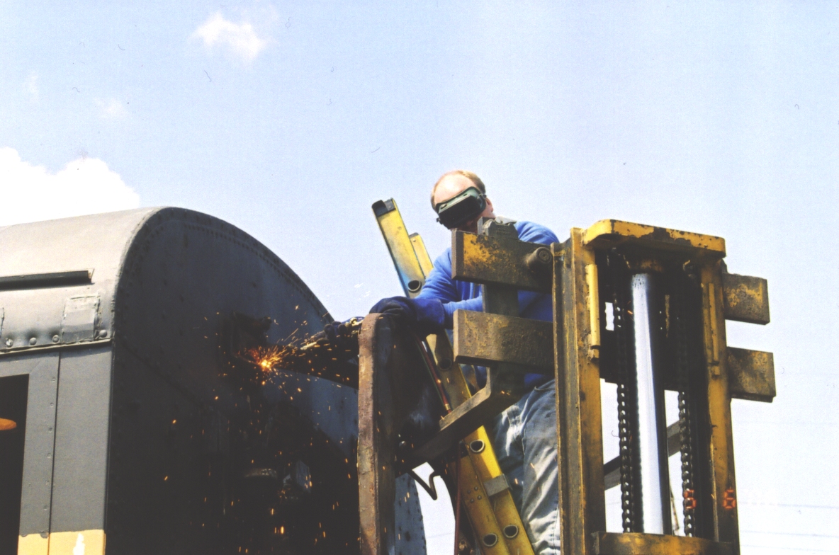
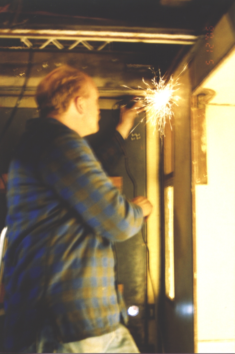
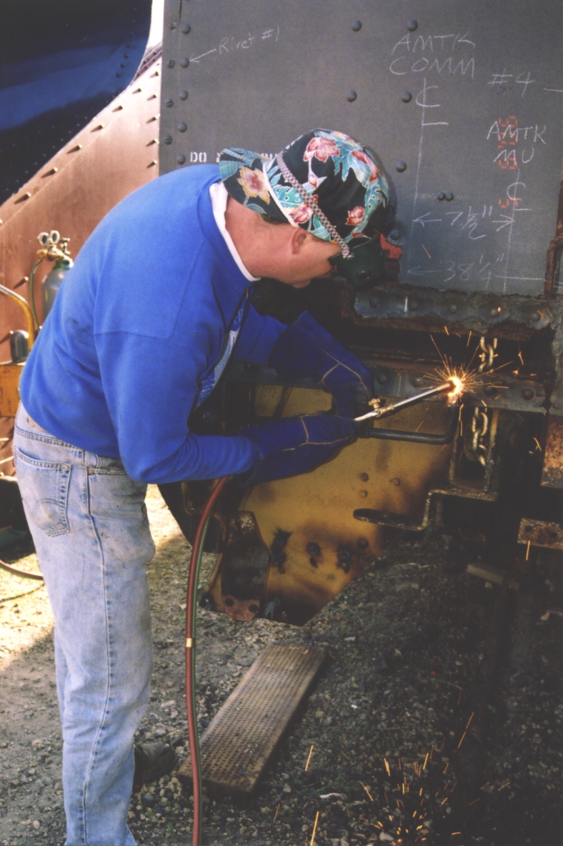 | Cutting off a grab iron. Even though they're in physical contact, the metal under the torch will heat up faster. Working carefull (and letting things cool if the other piece gets too hot) its possible to wash away the rivet without damaging the grab iron. |
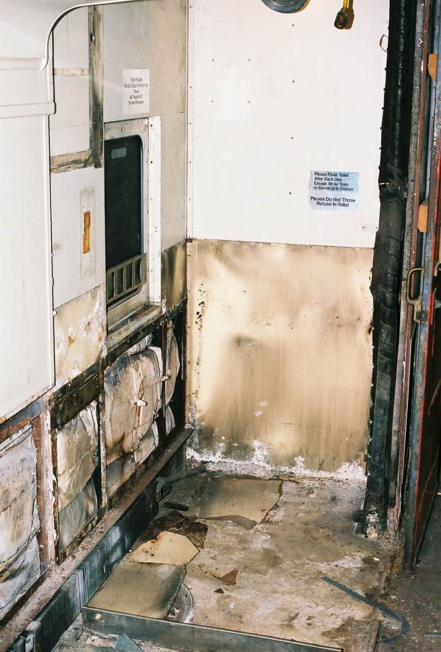
 | The floor just inside the door - a high traffic area, was so bad Amtrak replaced it in the 1970's. They also patched severe water damage to the bottom of the restroom walls. Now in 2006, I'm looking at restroom walls that have dry rot, delamination, and perforated aluminum facing, heaved restroom floors, soft spots in the coach aisle way, exterior skin problems - and the need to upgrade the blower/heater/chiller unit above the restrooms. One good result of Amtrak's repair - positive proof that the coach section was originally painted light grey. |
 | A needle-scaler does a good job of removing rust from steel castings. |
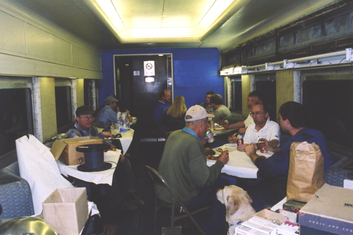 | Saturday was a regular museum work session. Our tradition is to order pizza Saturday night. (The delivery boy is well-trained!) With a dining car available, why not use it? |
 | The bottom of the casting, under the coupler, was hollow but 100% full of crud. We flushed it out with water and a poker. Crud traps moisture and promotes rust. |
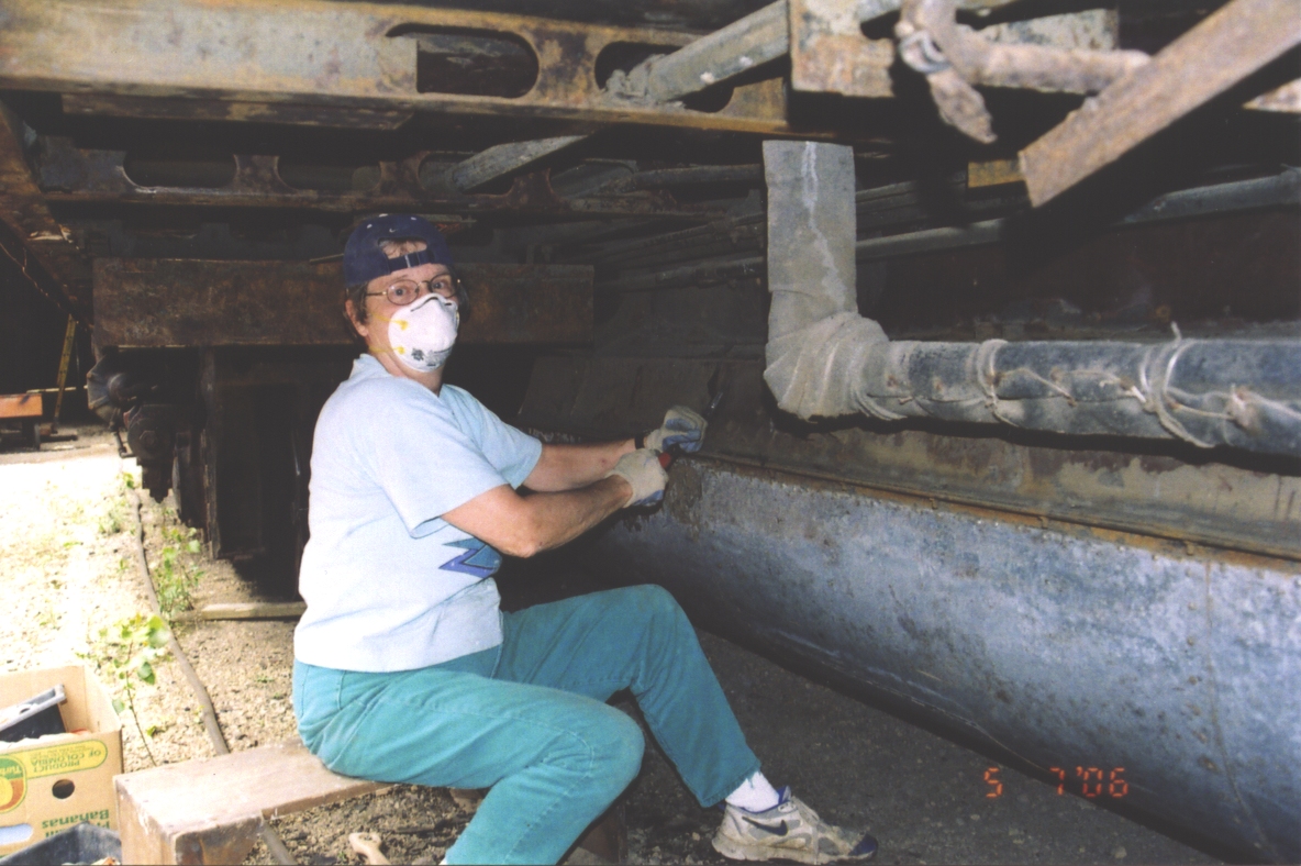 | This is the area where the transformers will be mounted. Mom is removing accumulated dirt and loose rust-proofing tar. |
 | We took great care to carefully disassemble the restrooms, unscrewing things without damaging them and marking each piece so that it could eventually be put back. It was a real fight - out of some 3000 screws, maybe 500 came easily. For the rest we used heat, penetrating oil, a hammer impact tool - or simply ground their heads off with a Dremel. It took all week. |
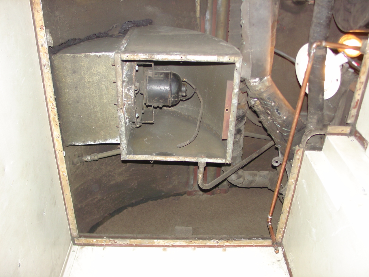
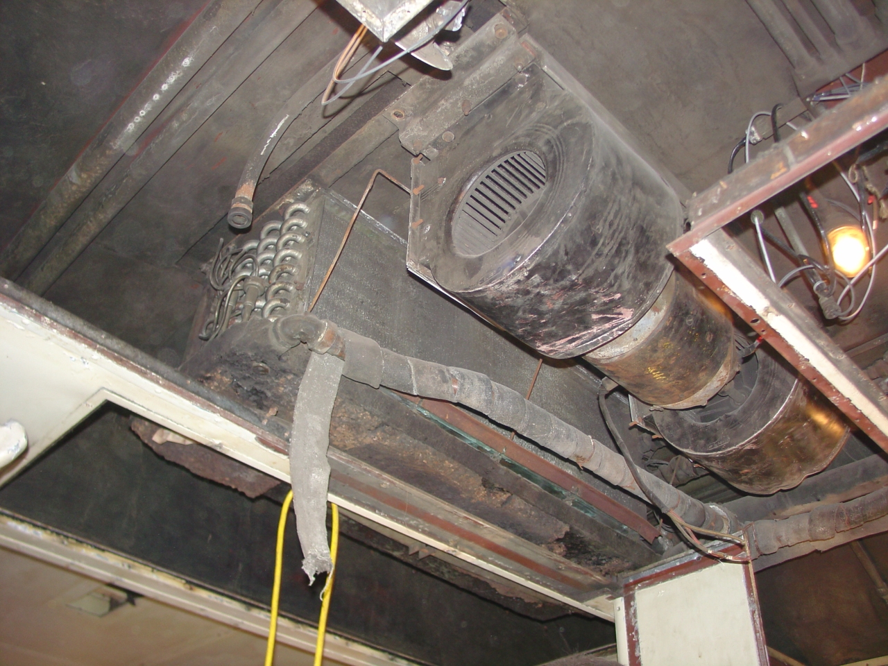
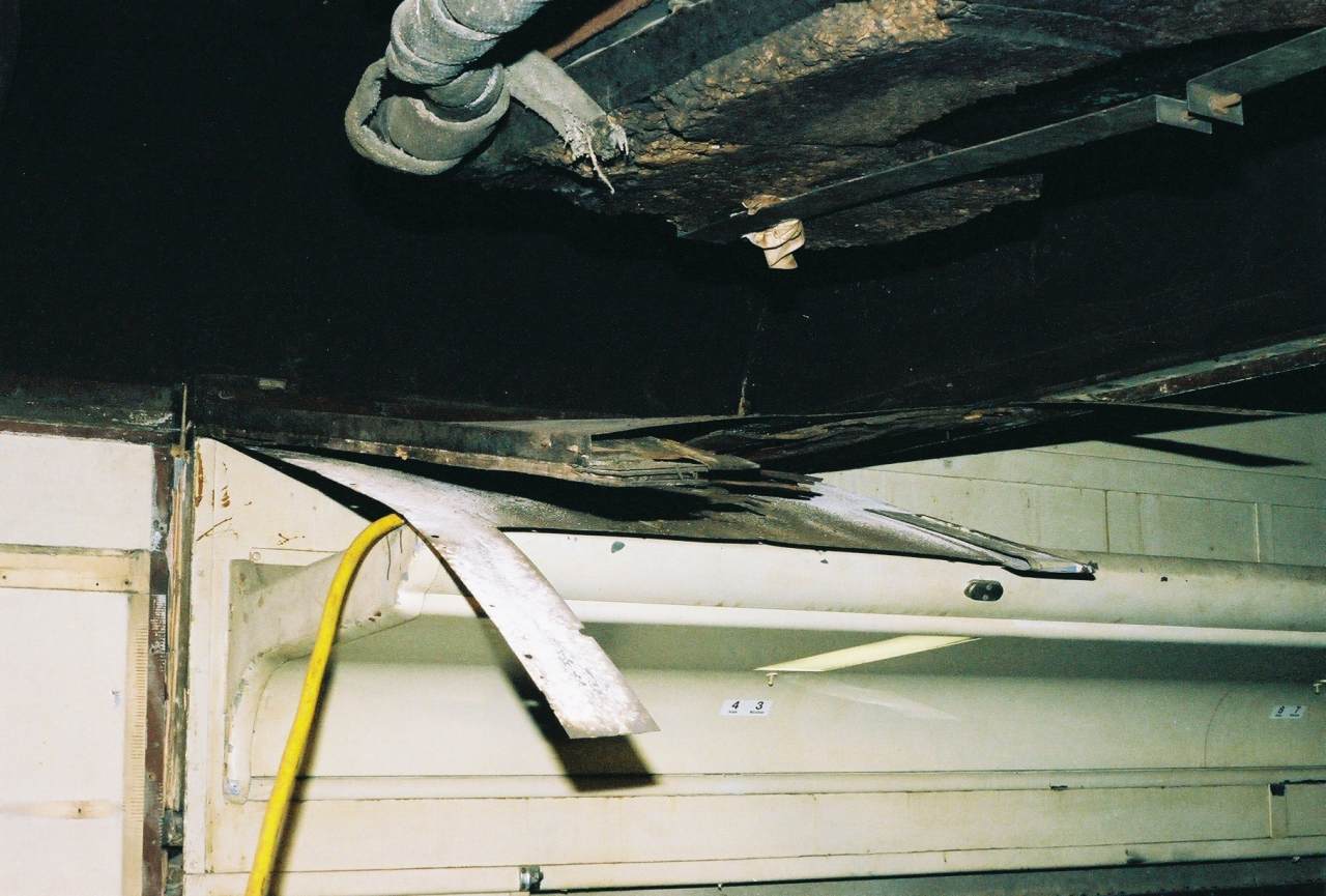
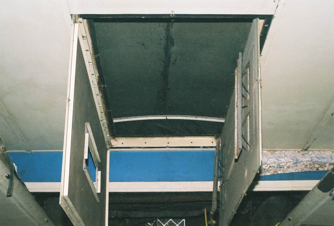
 | I was flat on my back to take this picture. This is the A/C blower above the restrooms, with the flexible duct into the heat exchanger coils. That would be "flexible" in the past tense - the old material just crumbled. Not visible is the wire-wound resister, used to drop the voltage for the low-speed setting. The wrapped pipe is the drain from the condensate drip pan under the coils. |
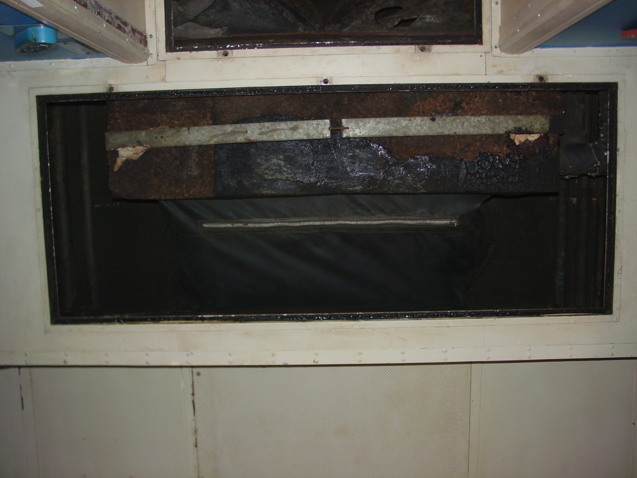 | The next ceiling access is the flexible connection between the heat exchanger coils and the car's overhead duct. (Note the zipper.) The steam overhead heat and R-12 cooling coils are together in the same unit. The strap we see supports the condensate drip pan, which catches condensed moisture dripping off the cold A/C coils. I didn't get the 1" of cork on the bottom. Dad, who is a HVAC mechanical engineer (he designs these things) thinks the water in the pan would be pretty cold, and the cork insulation is to keep condensate from forming on the bottom of the pan. |
 | There's one nice thing about working in the rain - it makes the leaks obvious. |
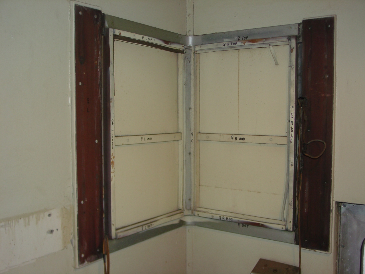 | Another picture showing how every piece of the restroom mirrors was labelled and photographed prior to disassembly. |
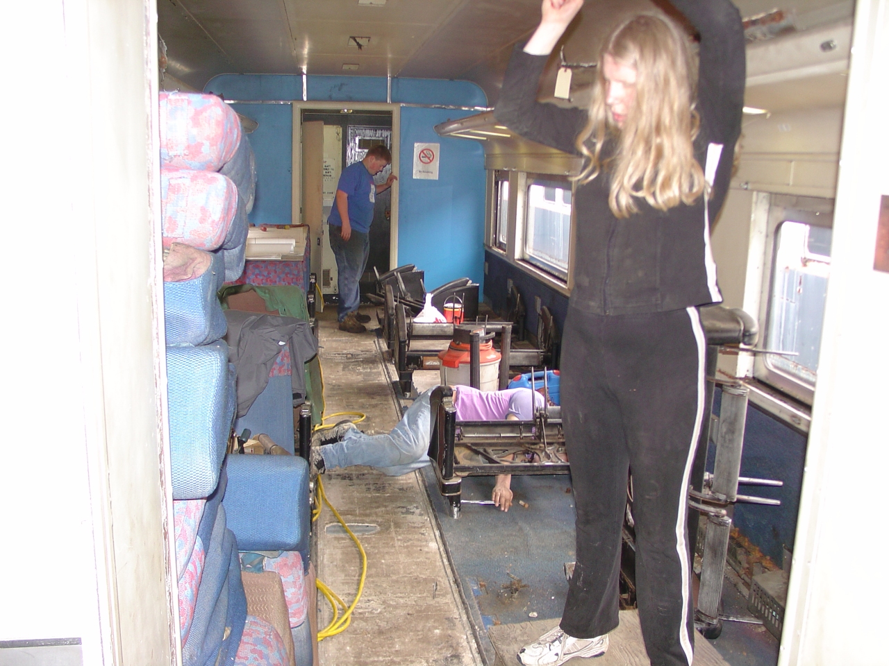 | The coach seats are coming out so that all the asbestos-containing materials will be exposed for the asbestos abatement crew. The stuff that will be reused was painstakingly removed by family, friends and museum volunteers under my close supervision, to prevent damage. |
 | Please watch your step! The coach seats were removed to a storage unit. (My garage.) |
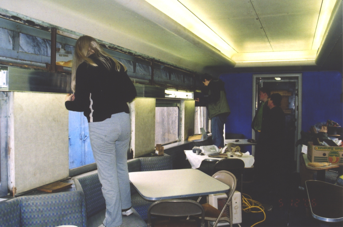
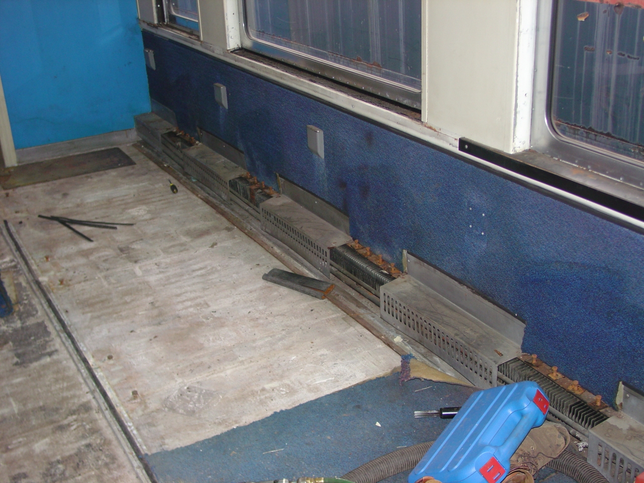 | After the energy crisis of the early 1970's, Amtrak had the political support and funding to refurbish heritage equipment and go shopping for new stuff. Here we have a good example of their refurbishing: Blue carpet on floor and walls with black plastic pound-in strips at the edges, and off-white paint above the window sill level. Not visible are the purple-and-blue slip covers encasing the original seat upholstery. Yes, it's sad they dispensed with so much of the car's original flavor, but the plain truth is the public likes clean shiny and new, and the heritage equipment was fully depreciated when Amtrak got it. |
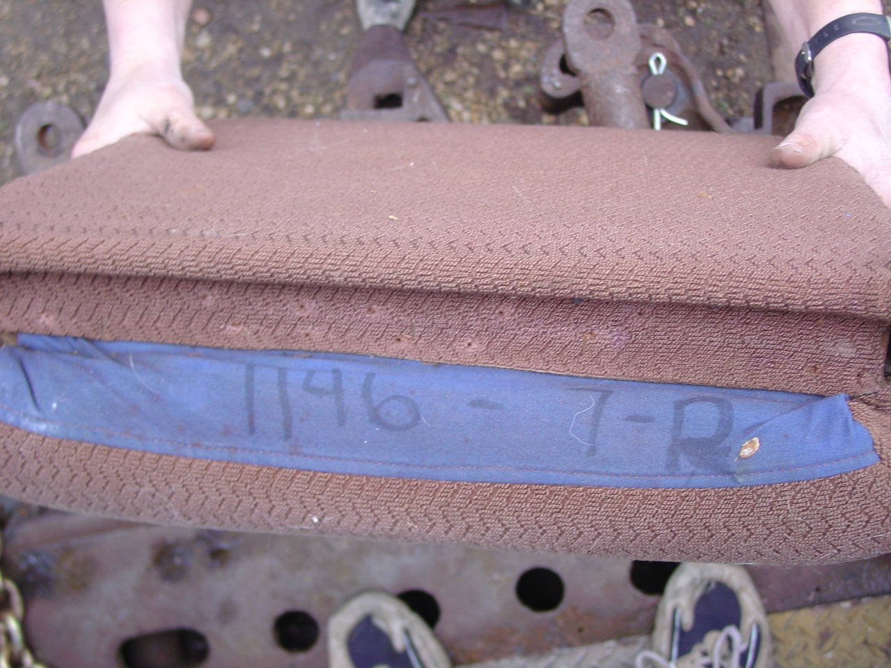 | Lookie what we found under the Amtrak slip covers! This is a seat back in original GN fabric, with identifying marks on the bottom. No clue what '7-R' meant. |
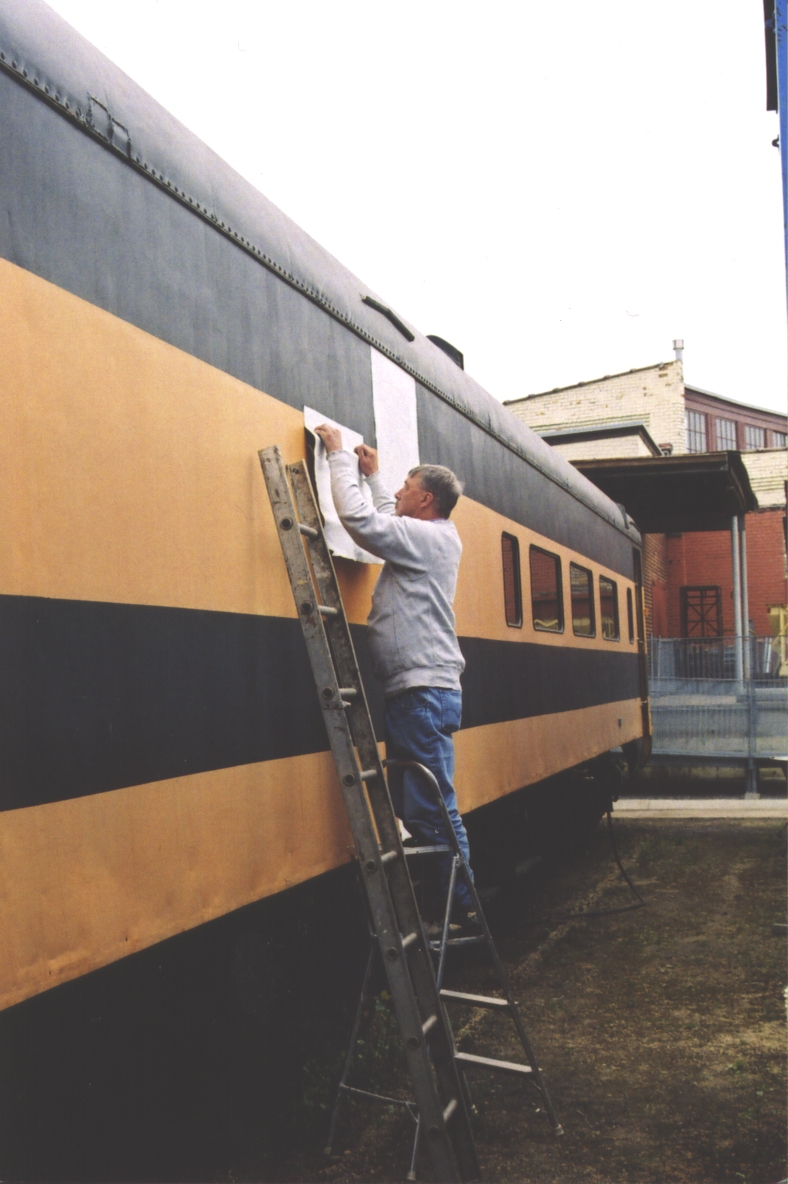
 | Another neat find: Under the carpet on the wall we found original lettering on the original paint. It was cut out as a sample of both the font and the paint color. |
 | Trying to loosen stuck screws. |
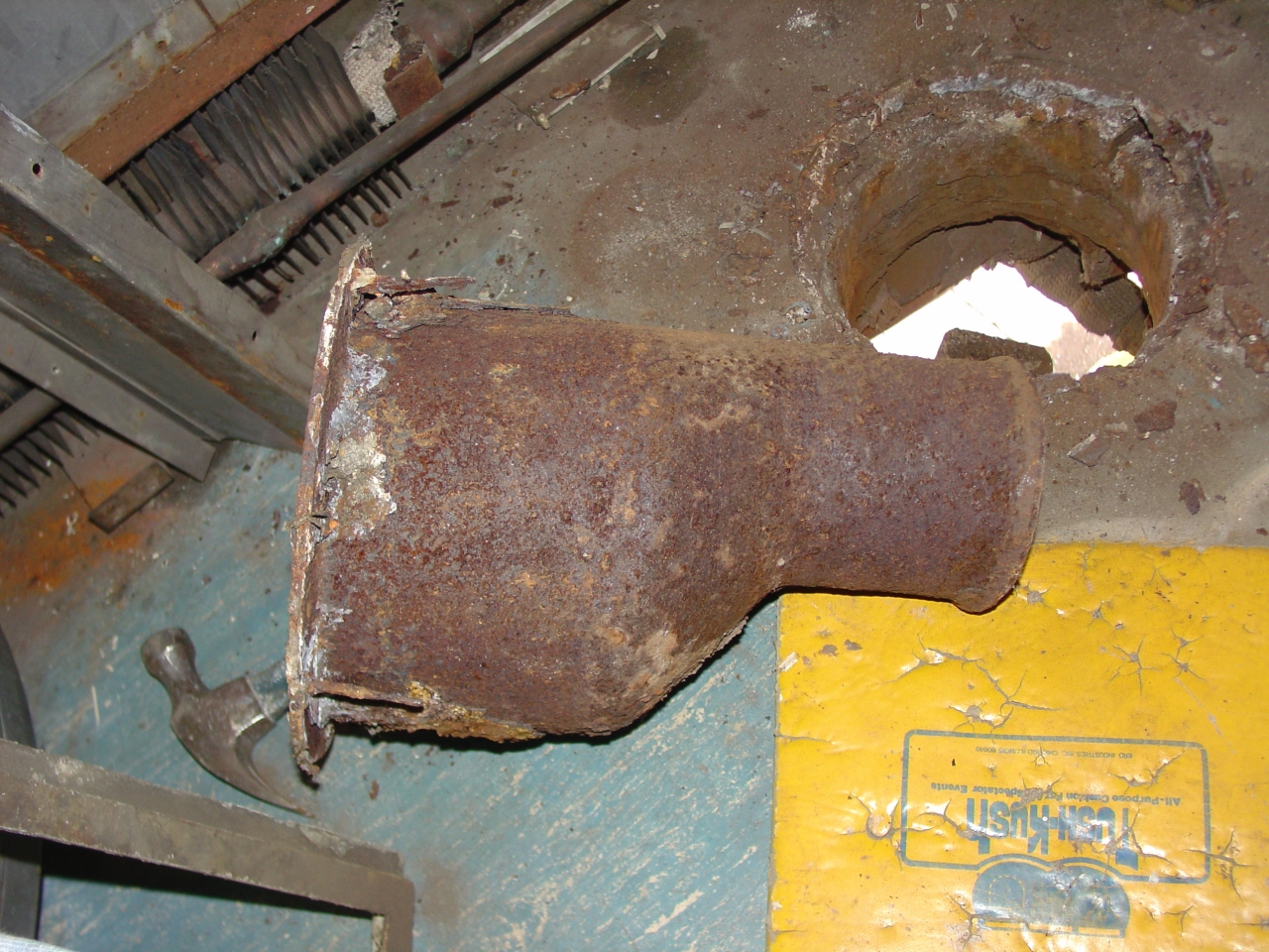 | Less glamorous but still interesting is this poop chute we popped out of the restroom floor. A museum volunteer had the idea of taking the rubber tube off the bottom and forcing it up and out with a track jack. This funnel portion is pretty heavy cast iron. |
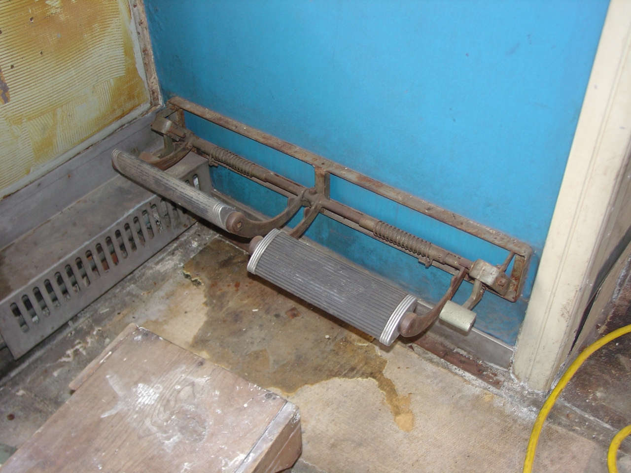 | As-built, the vestibule end was towards the front of the train. Therefore, the first row of seats had wall-mounted foot rests. |
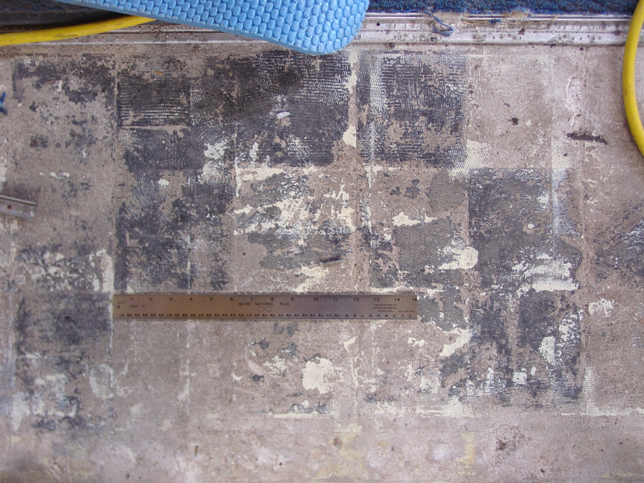 | This was interesting: From builder's photos I'd understood the coach floor was 9" square tiles. Yet when we lifted the carpet the pattern they left behind was a 6" grid. Cool. That'l make less waste when cutting down commercial 12" tile. |
 | Exhibit A: Water damage caused by leaky window gaskets. Yuk! (The four worst windows in coach - repaired just four years ago - are starting to leak again. Argh! Like this one, there was extensive pitting in the exterior skin where th gasket should seal.) |
 | The floor deterioration gave us a chance to study its original construction. Cross-wise in the center we see a steel Z-channel floor joist. On its top is a 1/4" wooden strip for noise deadening. The insulation between the joists is mineral wool with an asbestos paper backing. (Not visible is the thin stainless splash pan on the bottom. Pullman would have used steel - yea for ACF!) The floor structure is corrugated aluminum sheet, with a 1/2" thick profile. It was made by Morton, and sold as "Chanarch". The concrete is a light-weight composit, more for leveling than weight, called "Tucolith" from Tuco Products. Total floor thickness is less than four inches. |
 | The B-3-B emergency brake pull, after the facia panel had been removed. This kind with the 3/8" pipe doesn't exhaust the brake pipe into the car - it pilots an E3 relay valve under the car. |
 | Here's a good view of the restroom exhaust vent construction. The exhaust fan is mounted vertically in the right half of the duct - the blades in line with that vertical joint. Notice the roof insulation in the equipment space above the restrooms is lined with 1/8" Masonite and spray-on waterproofing. Also notice the restroom is contructed of 1/2" thick "Plymetal" - an aluminum faced plywood. It is de-laminating pretty badly. Possible reasons for the water damage: Roof leaks, A/C condensate, frozen/burst water pipes, clogged drain on the condensate drip pan, and general restroom humidity. Fortunatly we had rainy weather most of the week, and I can report never seeing a drop of moisture inside here. |
 | This is the same window as above, as the wall was being stripped down to the insulation. Notice the Masonite is crumbling from dry-rot, which easily catches fire. The peeling paint is another tell-tale sign of water damage. Also the fungus roots that grew on the insulation facing. All the more reason to get this stuff out of here! On a different note, the flexible connection on the steam pipe is required to allow the copper pipe to expand and contract. In a full length coach a 1 1/2" change in length between ambient and hot has been reported. |
 | This is a close-up of the bottom end of the aluminum restroom door frame. It's suffering from advanced electrolisys, where iron + aluminum + an electrolyte (water) make a battery, in which the aluminum is consumed. The white powder is the result of the chemical reaction. |
 | The end of a long day... |
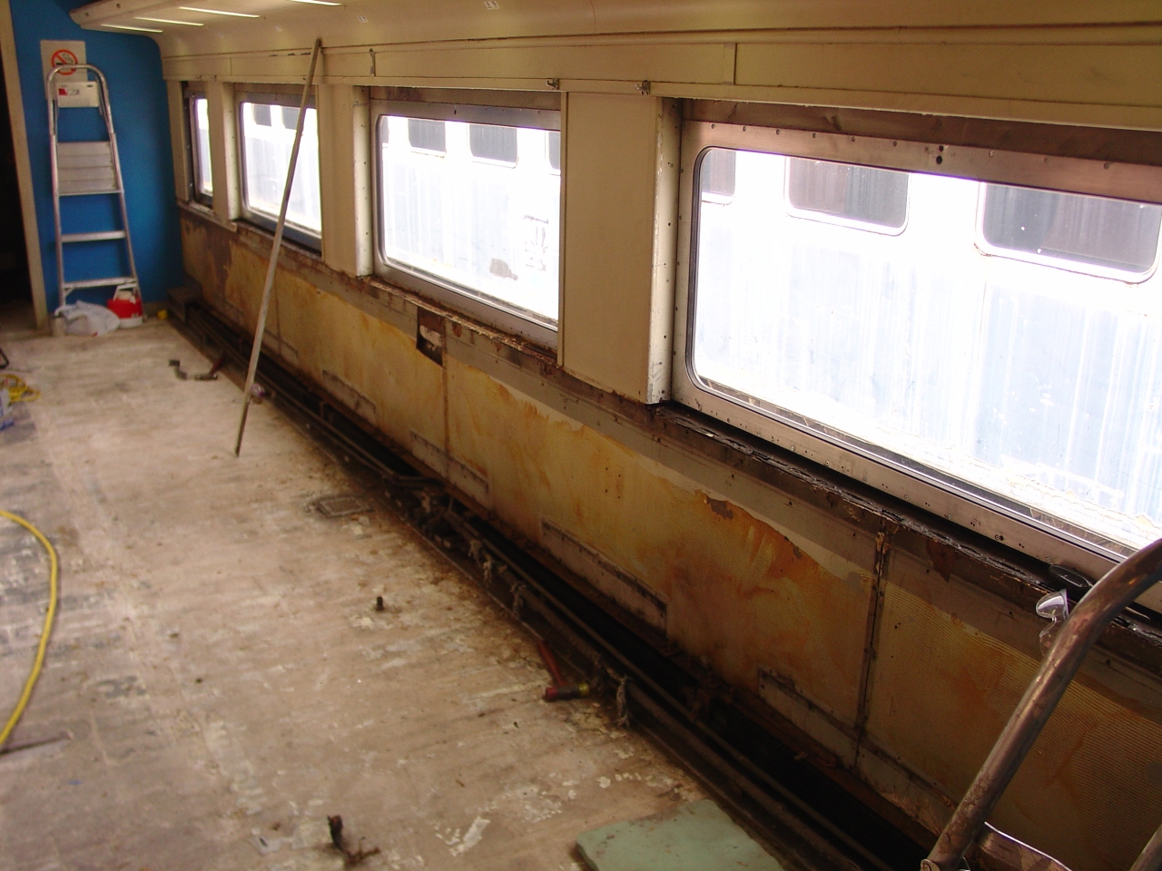 | The right side of the car after stripping. I thought it was interesting that ACF centered the joints in the masonite under the windows. |
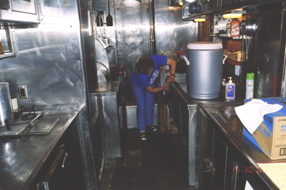 | In Randolph Mom had gotten the left side of the kitchen deep-cleaned. Now she's started on the right side. |
 | Some of the screws were pretty hard to reach. |
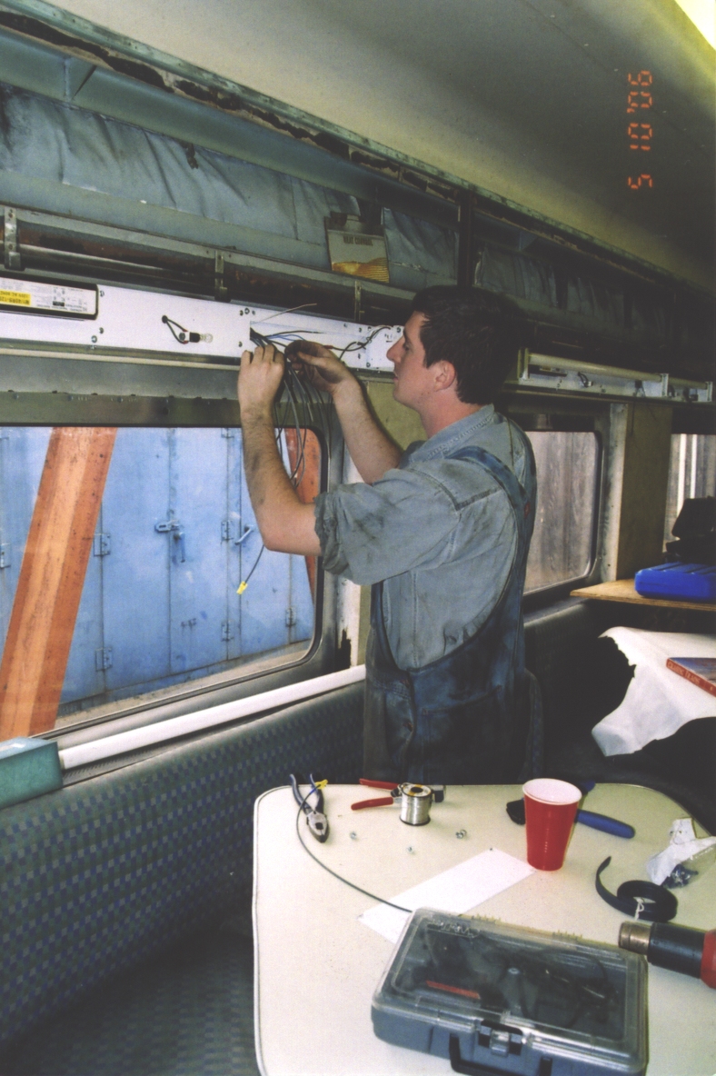 | Wiring the recently reworked dining room light fixtures. |
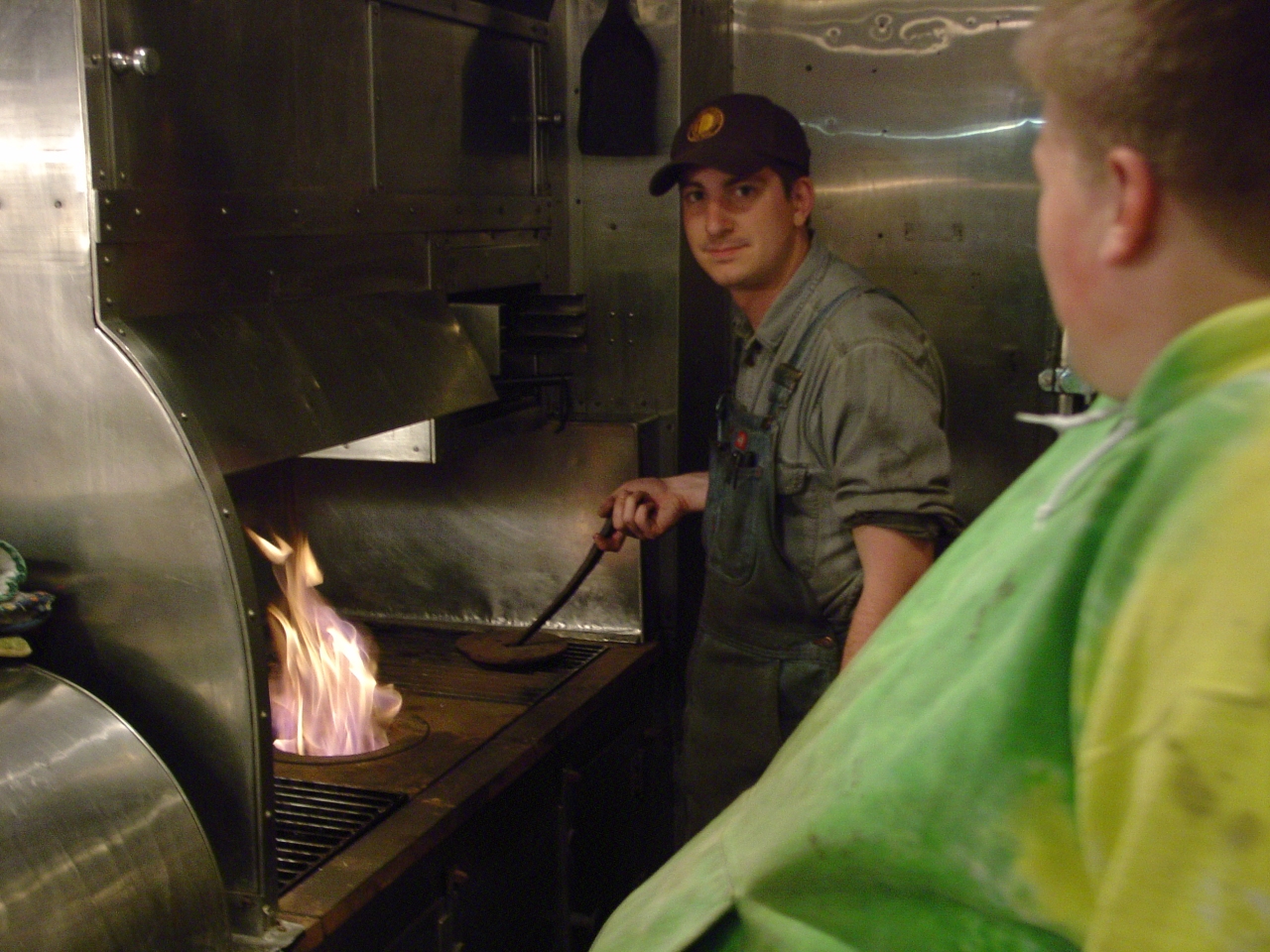 | Of course one day we had to grill on the stove. We jury-rigged the range hood blower again, filled the fire box with charcoal, and found a couple willing pyros to do the honors. We grilled on Thursday - volunteer night. We also ate three (microwaved) meals a day in the diner. (Thanks Mom!) 1146 also hosts the weekly Saturday night pizza delivery. |
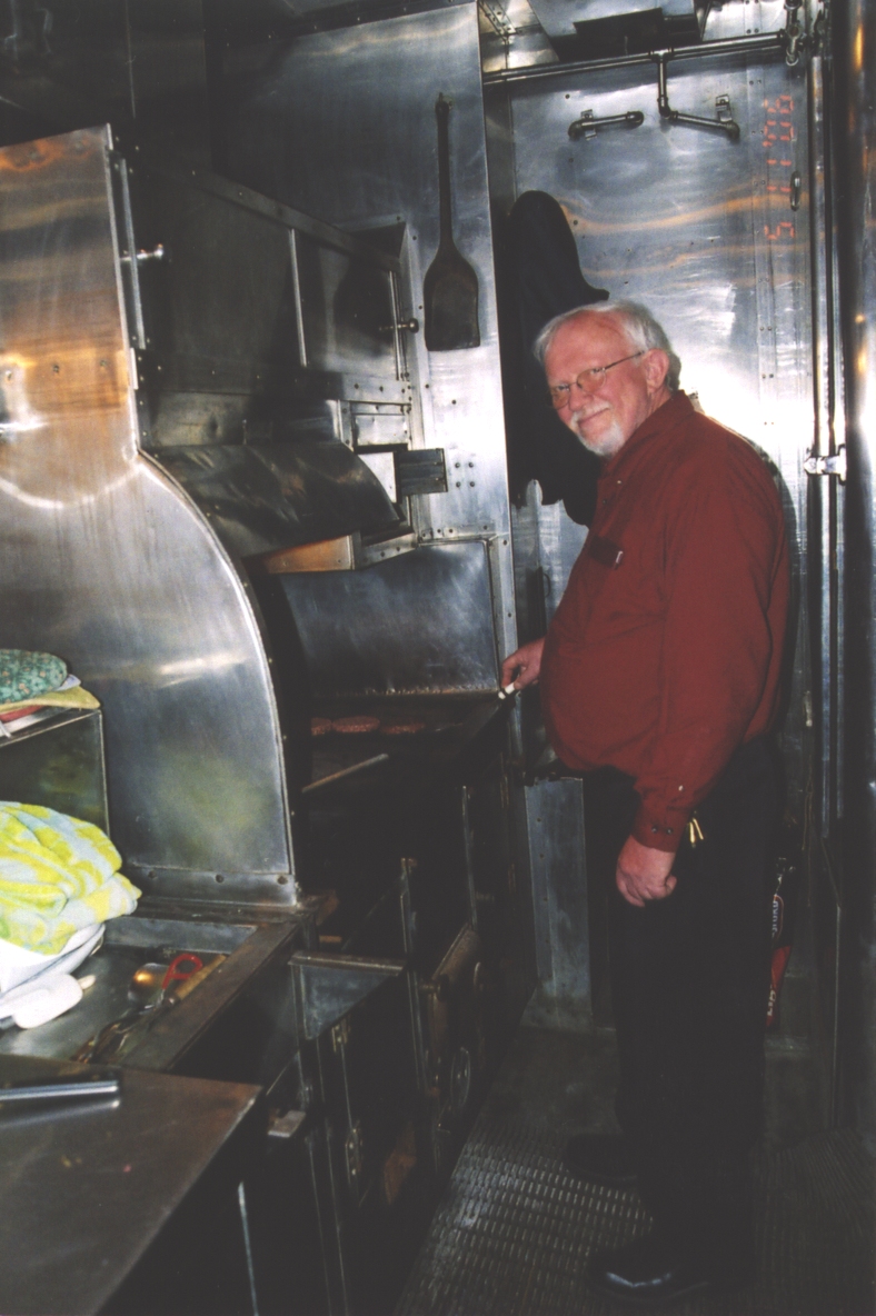 | I love the smell of sizzling steak! |
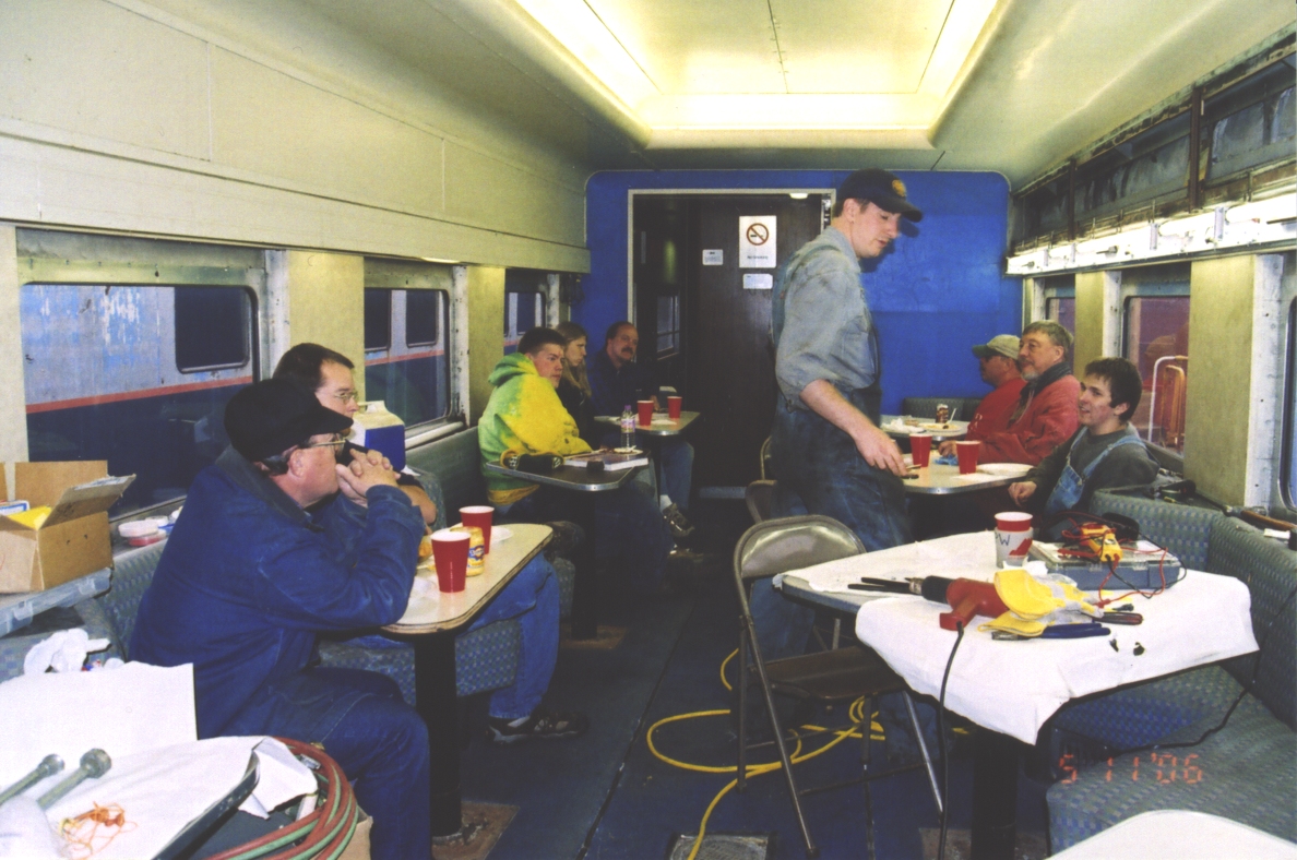 | The Jackson Street Shops crew enjoying dinner in the diner. |
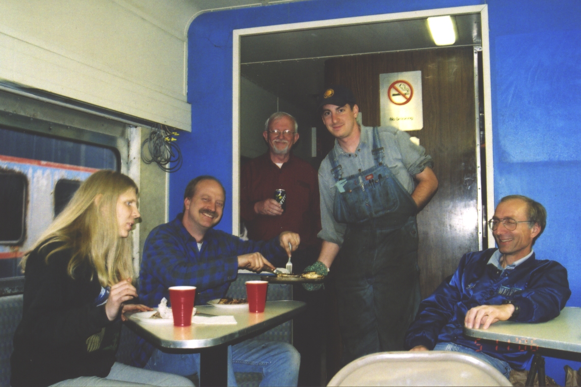 | My friends have some pretty good senses of humor. Clown for the camera! |
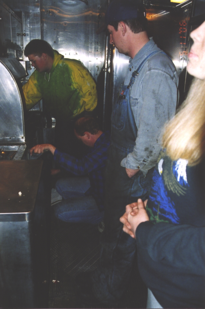 | Working out the proper way to shut down a hot charcoal stove. |
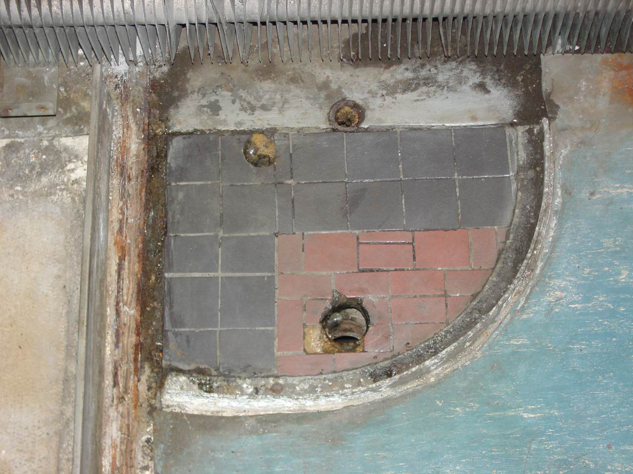
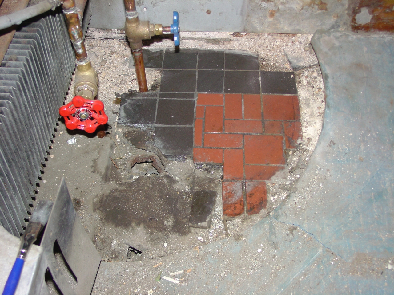 | Under the lavatory in the restroom we found a remnant of the original restroom floor tile. Very cool. |
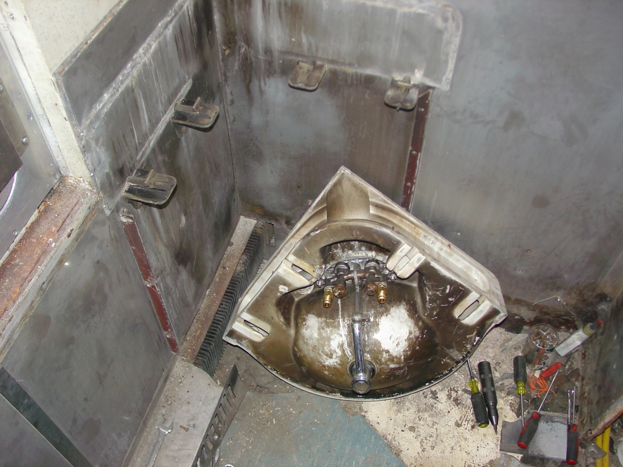 | The porcelain restroom lavatories are supported by four brackets, and secured with brass T-bolts. This also shows how the faucet body mounts, and how the drain lever works. (Despite its complication, it's really just a single lever arm with the fulcrum at the end of the chrome drain extension.) |
 | Fitting the aluminum covers to the light fixtures. An ice pick did a great job of getting screw holes to align. When the dining room is finished, these will be painted a metalic bronze color. |
 | Just right of the end door is the pipe chase. Left-to-right we have the drain from the condensate drip pan, steam return, steam feed with manual shutoff valve, hot and cold water pipes, and A/C refrigerant feed and return. |
 | This shows the restroom exhaust fan arrangement a little more clearly. It also shows how the ceiling was mounted: The walls went in first, and extended a couple inches above the ceiling. Aluminum L-channels were screwed to the walls (with fabric tape between to eliminate squeaks.) Then the ceiling panel was hoisted up and quick fastened with a few countersunk screws - just enough to hold it. Lastly, aluminum batten strips were fastened with truss-head screws about every four inches. |
 | When nothing else would free a stuck screw, a Dremel Moto-Tool with a cut-off wheel could grind the head off without damaging the surrounding metal. (If one was careful.) We went through several dozen of those wheels. |
 | This is craftsmanship! The wall above directly above the restroom doors is a separate piece. Not only is it clamped top and bottom, with a batten strip on the front and back of the joint, but they saw fit to route the edges for a key in the middle! |
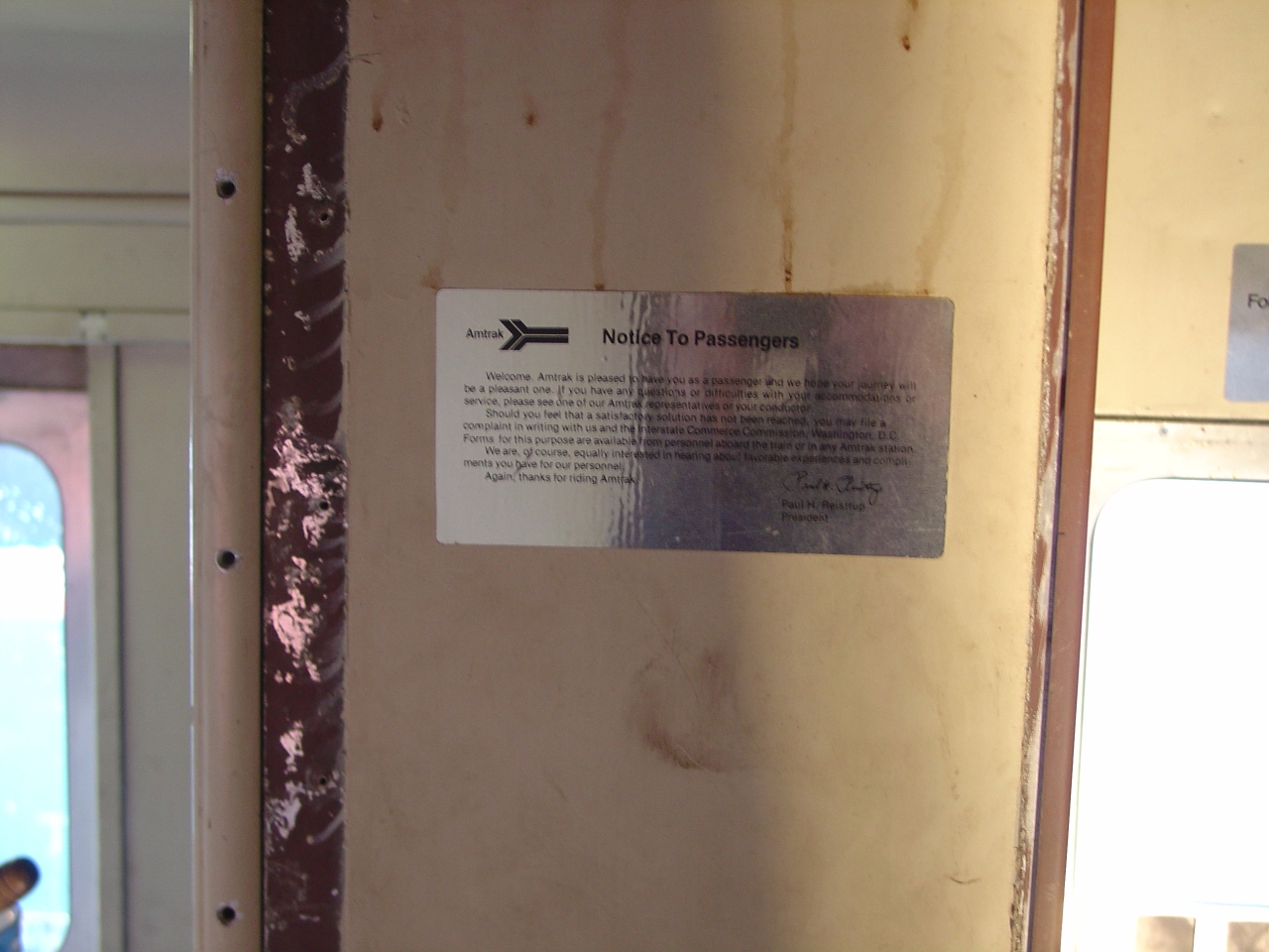 | Paul Reistrup was Amtrak's president from early 1975 until mid 1978, so this placard on the wall helps date when 1146's interior was reworked by their shops. His tenure was right after the energy crisis, and Amtrak had political support for buying new equipment and refurbishing old. |
 | The men's room is gone, giving us a good view of the overhead air conditioning equipment. |
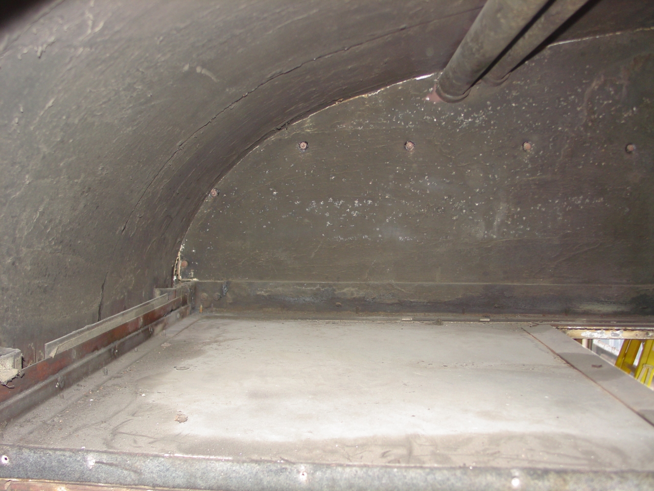 | This is the inside of the equipment area above the restrooms, which projects over the first row of coach seats. The walls (left) were built first, and the ceiling suspended from them. Where there weren't walls, structural steel members support the ceiling. The roof insulation in the equipment area is covered with 1/8" Masonite with a sprayed-on coating. That vertial sheet dead ahead may be a pain. On the opposite side Amtrak's wallpaper is falling off, revealing a very deteriorated aluminum facing and delaminating plywood underneath. (See two pictures below.) |
 | Looking at the footprint the restroom wall left behind. That's the equipment area projecting over the first row of coach seats at top. The inside finish of the exterior wall is quite different in the restroom, compared to the coach section. |
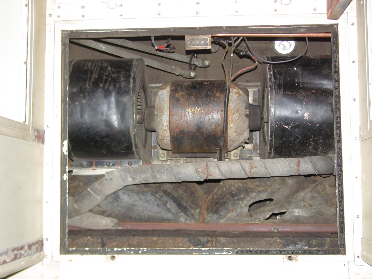
 | Six-foot threaded rods were used to lower the blower assembly to a level where we could easily handle it. This had to happen after one restroom was removed, because the assembly is four inches wider than the hallway. I've seen two methods used to upgrade the blower to 480 volt three-phase. Plan 'A' is to replace the blower motor. Unfortunately, most 480v motors won't duplicate the dual speed function of the original. Plan 'B' is to replace them with two independent squirrel-cage blowers. Northwest Rail Electric sells a unit built with this plan. Running one instead of both simulates the low-speed setting. |
 | Lowering the blower was a lot like an old-fashioned barn raising - everyone in the neighborhood gathered to help. |
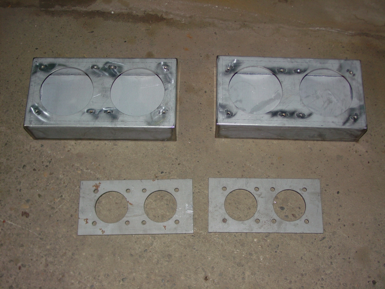 | I ordered these thinking we'd be doing vestibule steel work: These are HEP connector mounting plates and COM/MU connector boxes from NWRAIL. They're laser cut, so nice and accurate, and I figured it would be easiest to provide for the HEP install if mounting points were incorporated in the new steel work. |
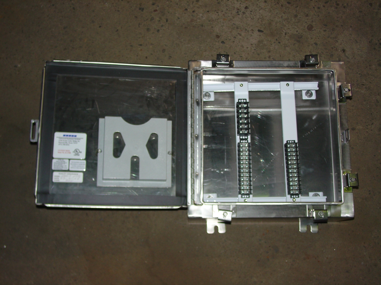 | This is a stainless junction box for the COM and MU wires. There will be one under each end of the car. There are enough terminal strips here for COM, but with another mounting bar and set of terminal blocks, it can also accomodate the optional MU wires. |
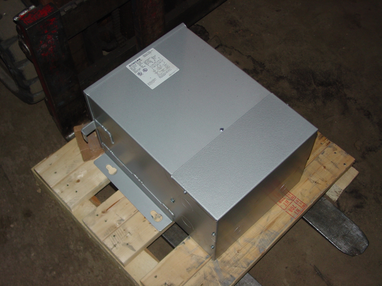 | Another project I'd had ready for the work week was installing the 15kva 480 delta to 208 wye step-down transformers. This is one of the three. Right now 1146's 208 panel is hot-wired to the building, and installing these transformers will provide 480 for blowers, etc. When funding permits I'll build the correct shore-power equipment. |
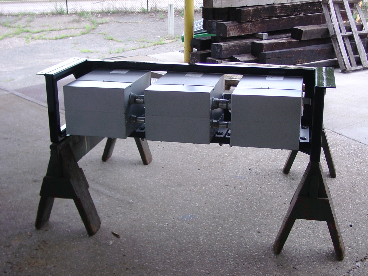
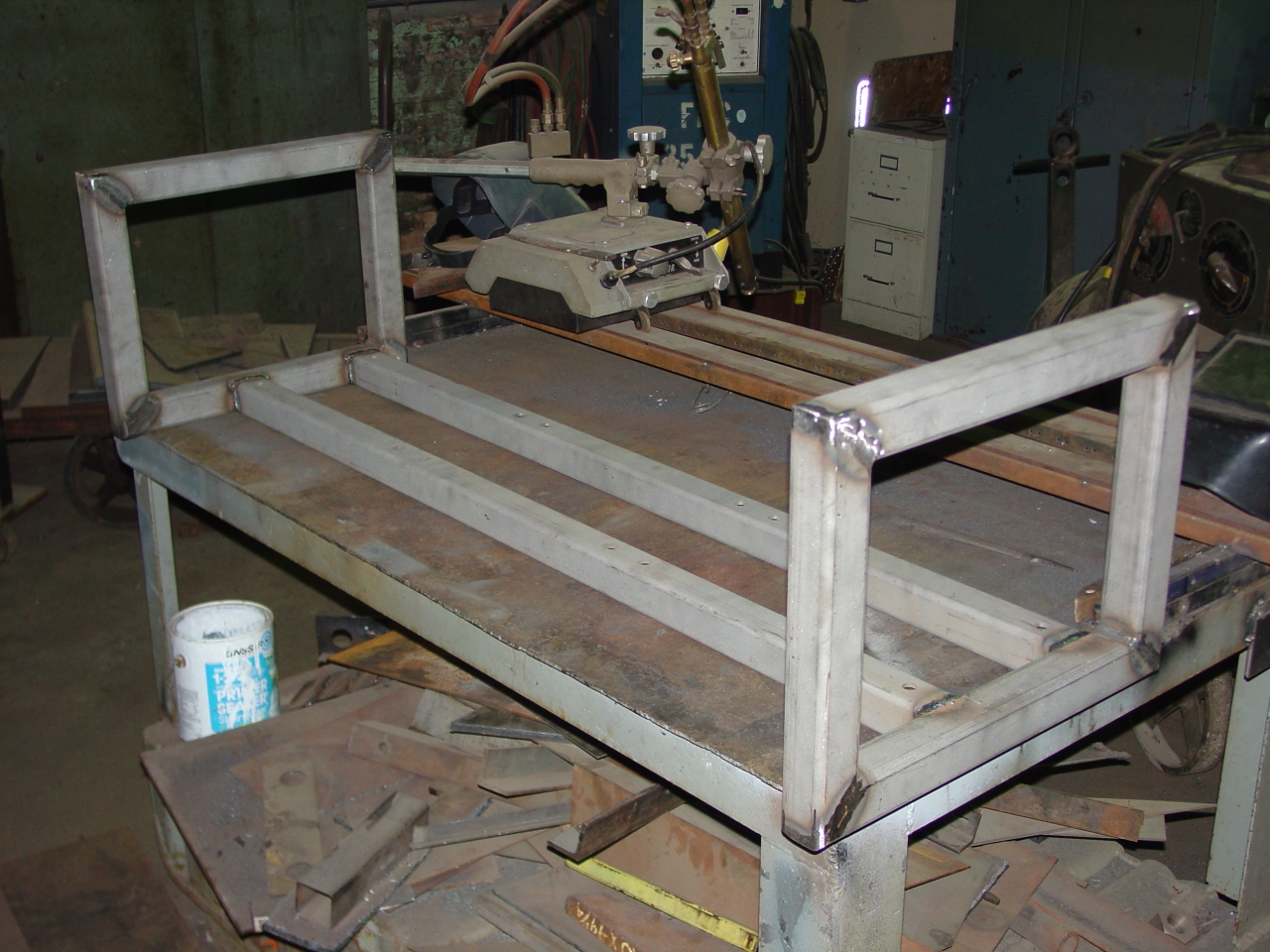 | After the work week, I wanted to work on something different for a change. The steel had arrived, so I set to fabricating the transformer rack. Here's the basic frame, made from twenty feet of 2"x2" 3/16" square tube. Yet to come are the back, mounting rails, and gussets. Tube is stronger for its weight than any other steel shape. Welds were vee'd for good penetration, and go all the way around for strength and to keep water out. Parts were sandblasted just prior to welding to improve paint adhesion. The horizontal rails are under the heaviest part of the transformer, while the side extensions are there to protect the transformer's sheet metal wiring enclosures. Dimensions were sized to permit access to all screws. |
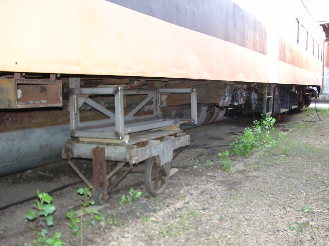 | Before building the mounting ears, the transformer rack went under the car for a test-fit. It has a smaller profile than the battery boxes, and provides room to work on the water reservoir behind it. Reworking the conduit runs will take some time. |
 | Assembly of the transformer rack is finished. Per Amtrak specs, there are separate conduits for the different voltages. The next job is cleanup of the mounting location under the car, building mounting rails, and painting. |
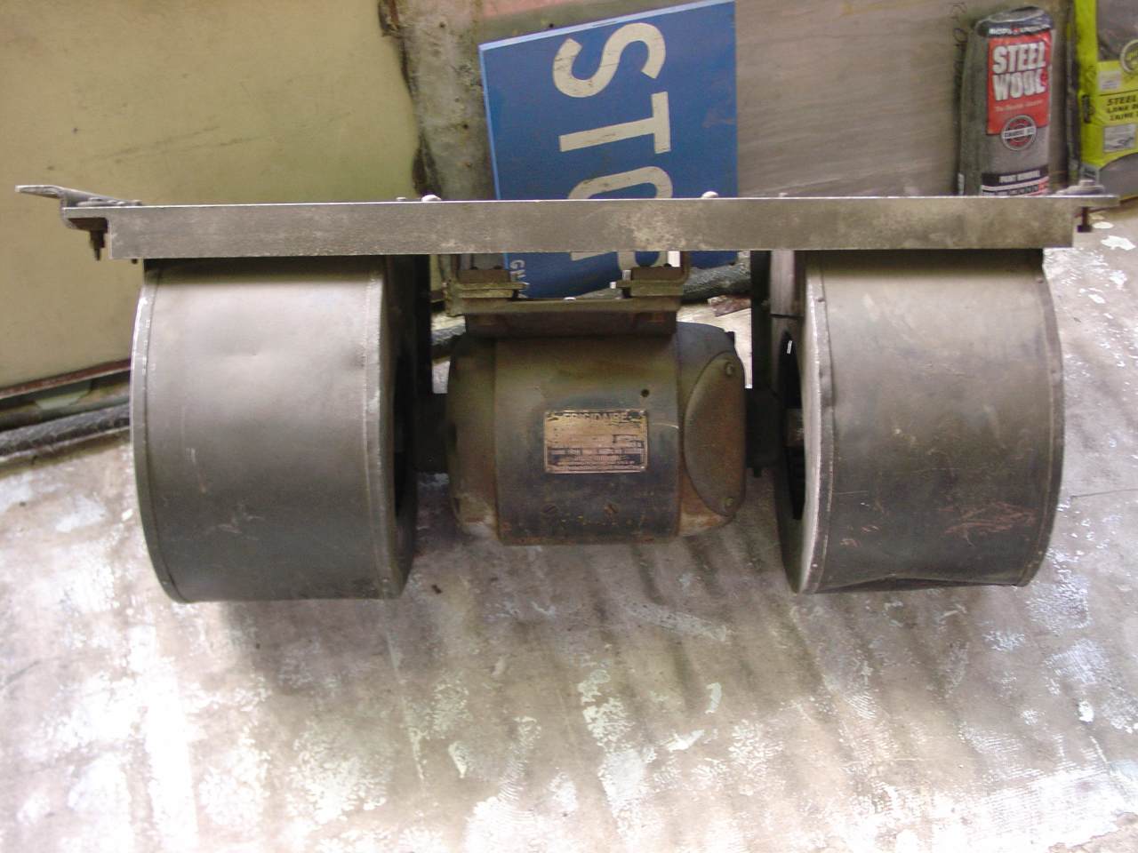 | The blower posed for its portrait. It's a Frigidaire model A7181 with a one horse DC motor, turning 1250 RPM at 30 volts / 32 amps, and 1750 RPM at 36 volts / 27 amps. |
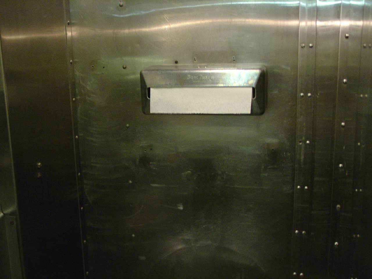 | A small "feel good" victory: The Scott 50-count paper towel dispenser has been hung in the kitchen. |
 | A sample of original women's restroom ceramic floor tile, next to the Amtrak rubber tile. The silver area below the heat register is one piece with the back plate of the register. |
 | The B-end 32vdc trainline connector. The lug on the left has been soldered and taped. The Pyle-National connector is not new - just rebuilt. |
 | A museum docent made interpretive magnetic signs for rolling stock. I think it's really cool. |
 | The trainline connector is done, and preparations to replace the right collision post continue. Amtrak's car number on the end door shows clearly, too. |
 | I cut away the smallest amount of end sheet necessary to splice the collision post - though I'm still debating between a splice or full replacement. The later is more work, but requires zero engineering because everything would be per the original drawings and specifications. |
The rest of June was spent on two major projects: Preparing the location where the transformers will go, and preparing to repair the BR collision post. There were also two minor victories: The kitchen napkin dispenser has been hung, and the B-end 32vdc train line connector is finished. Stainless screws for mounting the kitchen fold-down lavatory, pot hooks, and the one loose refrigerator door are on order.
To prepare for mounting transformers, I've been carefully removing any old mounting brackets (head-knockers) that won't be needed again. I'm also reworking the electrical conduit to some refrigerator lights and a convenience outlet in the dining section. Then I need to fabricate mounting rails, run new conduit, and paint the whole works.
I've been studying two options for repairing the collision posts. Option 'A' is to cut out as little as possible, and bury the splice behind the designed-in shear plate. A few more doubler plates would be required, and would obviously look repaired. Option 'B' is to replace the entire post. That turns out to be more difficult because it's solidly riveted and welded it above the ceiling, and partly buried in asbestos insultation. For now I've cut away only enough end sheet to do option 'A'. I got a quote on new I-beam which meets the bill of material's specifications: It's about $550 for a 25-foot stick, and is not stocked locally. Hmmm. My cash-flow spreadsheet says I'll be placing the order in early August. The shear plate is 1/2" l.a.h.t., and I've been quoted $1500 for a 4x8 sheet. That low-alloy high-tensile steel (Cor-ten) is perhaps 50% more than A36 mild steel.
My plans for July are to mount the transformer rack; the kitchen fold-down lavatory, fridge door, and pot hooks; wire up some fridge lights; finish the left-side valence lighting in the dining room; and maybe get back to restroom demolition in prep for asbestos abatement. (Which the budget spreadsheet tells me might happen in early 2007.) I also need to figure out an enclosure for the 480-volt breaker panel before I can wire the transformers.
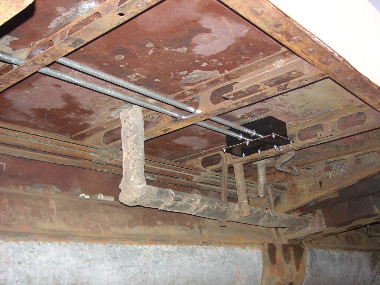 | Much of July went into this picture: I've been carefully removing no-longer needed equipment brackets (two more to go) and reworking the electrical conduit. This area is where the transformers will be mounted. The junction box I fabricated. A conduit through the floor feeds the light in an under-cabinet refrigerator. One new conduit will feed an electrical convenience outlet in the dining room. The other will feed a stand-by air compressor. Notice the lid is keyed to only go on one way. |
 | The transformers will be mounted just to the left of the access hatch in the middle of the water reservoir. |
Still to do before I can mount the transformers:
On the bad side, I lost $16,000 on an effort to acquire GN International tail car 1195 "Port of Seattle", and donate it. The next time someone pitches a wonderful idea I will be a lot more skeptical.
On the good side, I've made some progress on the location where the transformers will be mounted. The circuit to the light in the refrigerator under the cupboard is finished and working. Turns out Amtrak added that. The conduit to the dining room convenience outlet is nearly finished, and the air compressor rough-in is done. I've also gotten some copper brazing supplies and started reworking the straight air line into air compressor & toilet air lines. Just for fun, I also hung the kitchen's fold-down lavatory (plumbing not hooked up yet) and a refrigerator door that was missing its hinges.
On the bad side, my digital camera went blind in one eye, and the manufacturer turns out to have a terrible repair reputation. I always carried it in the trunk so I'd have it handy, but I guess it got cooked. For now, I'm back to my old reliable 35mm Pentax.
One more on the good side. A friend, who used to own a Burlington Budd car, is downsizing his residence and has given me several useful gifts. Among them are a Thomas & Betts 8 awg to 500 kcmil crimping tool, a Morten step box, a dead-weight gauge tester, a blue flag and flashing blue light, a jack and an extension cord, and several other interesting items. Thank you!
Looking ahead, my losses on 1195 - coupled with rising interest rates - dictate that I cannot make any major purchased for many, many months to come. So look for me to be doing a lot of piecework. Maybe I'll learn how to reupholster coach seats this winter...
Very little news. I did start stripping Amtrak slip covers off the coach seats. (My garage was starting to smell like mildew.) A few interesting discoveries:
 | Amtrak baffles me! They carefully crafted these slip covers, complete with reinforced openings and ready-to-use velcro. Then they put them on 8400 and 8401 (1145 and 1146,) crudly cutting openings with scissors, and using tacks and staples rather than the velco. Weird. |
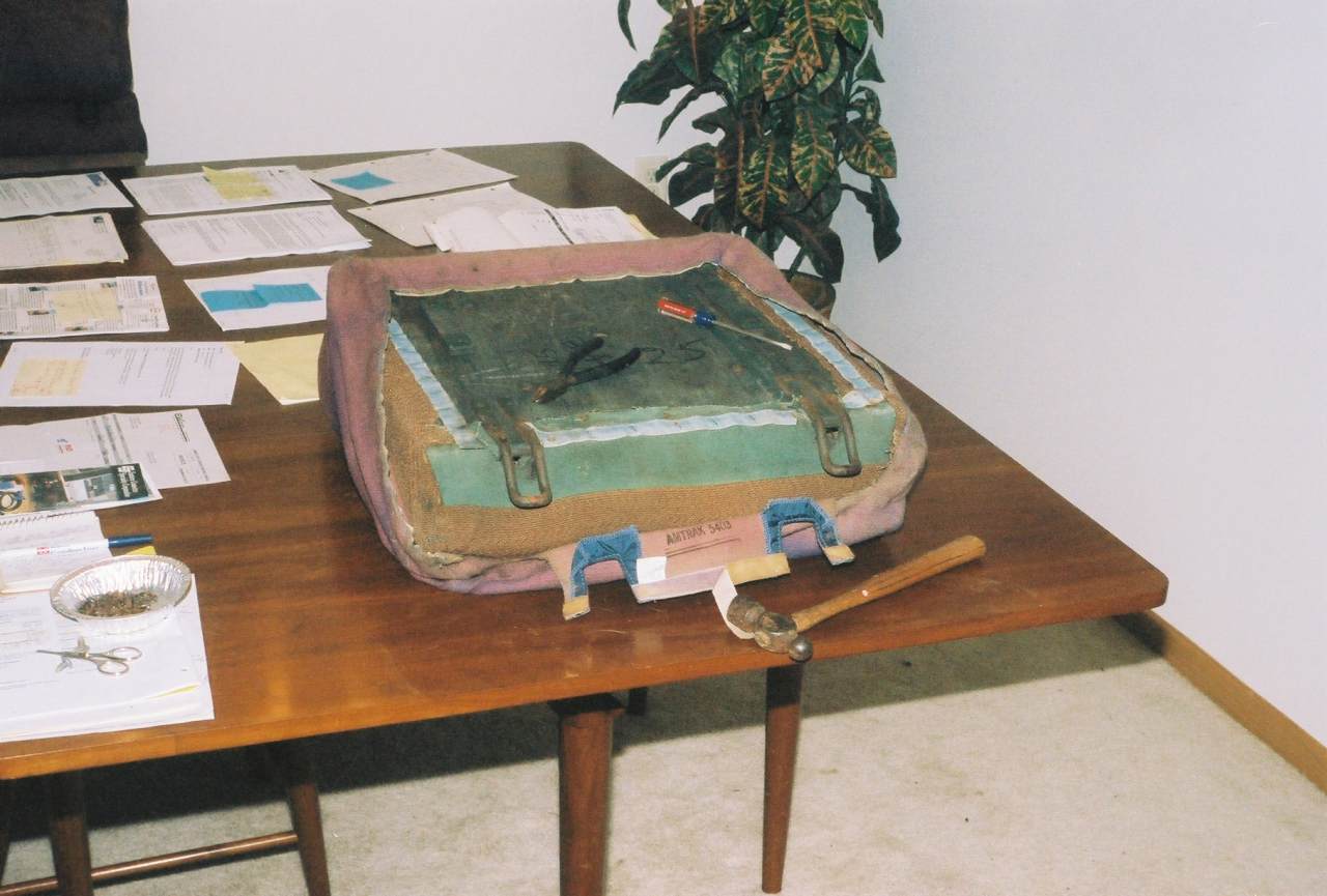 | With the slip cover half-off, we can see the velco tacked to the seat bottom, and stitched to the slip cover. The hammer is exhibiting both halves of the slip cover velco are there. Note "Amtrak 5403" printed on the inside of the slip cover. (Is that the car they were intended for? AMTK 5403 was a 1940 Budd Stainless 54-seat coach, formerly SCL 5403, and ACL before that.) |
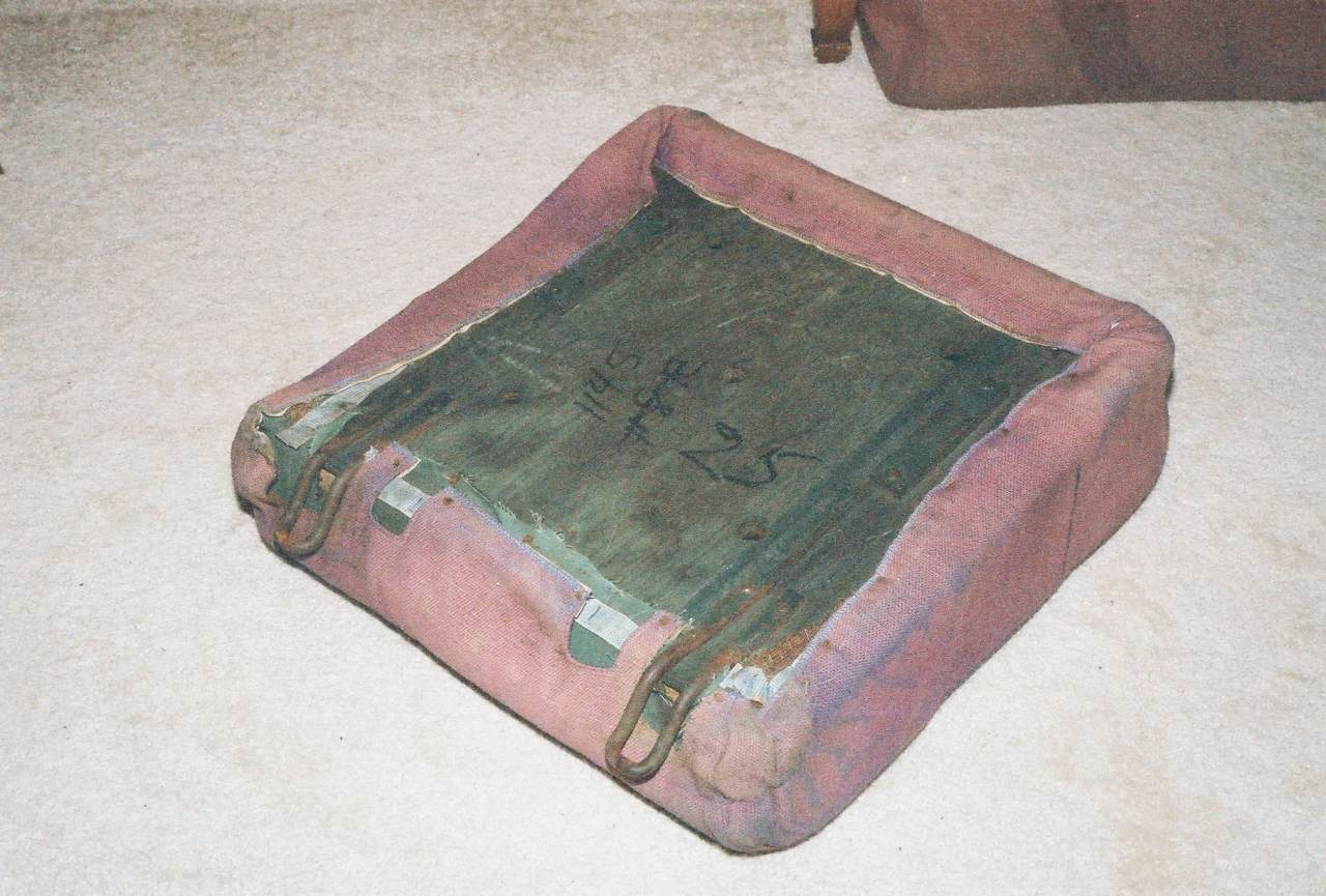
 | Here's a seat bottom. This is GN fabric, though I don't know whether its from 1950 or whether the GN shop forces were excellent craftsmen. Whichever, its in awesome condition for its age. (A reader replies that railroads typically reupholstered about every ten years, depending on usage, and kept at it not knowing whether the Feds would permit them to drop passenger service. Evidence supporting this: I did not find any pine trees, which decorated some seat backs in the builder's photos. Also the Minnesota Transportation Museum has three bolts of upholstery fabric which came from BN's Como Shops. Evidence confounding this: MTM's three GN streamlined coaches in service, 1096, 1097 and 1213, all have the same seafoam green vinyl upholstery. |
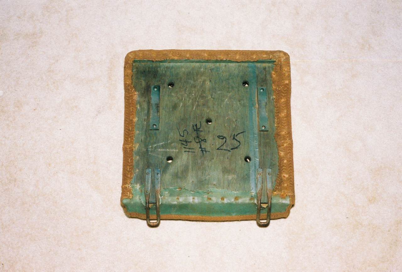 | Same seat, flipped over. This one says it came from 1145, but I've no idea where "#8R" would have been. |
I laundered the slip covers - wanted to keep fabric samples but loose the mildew smell - but about 50% ripped and started to unravel. Anyone want an Amtrak fabric sample? I'm eric underscore d underscore hopp. Yahoo! dot com.
I started October cleaning little parts in my garage.
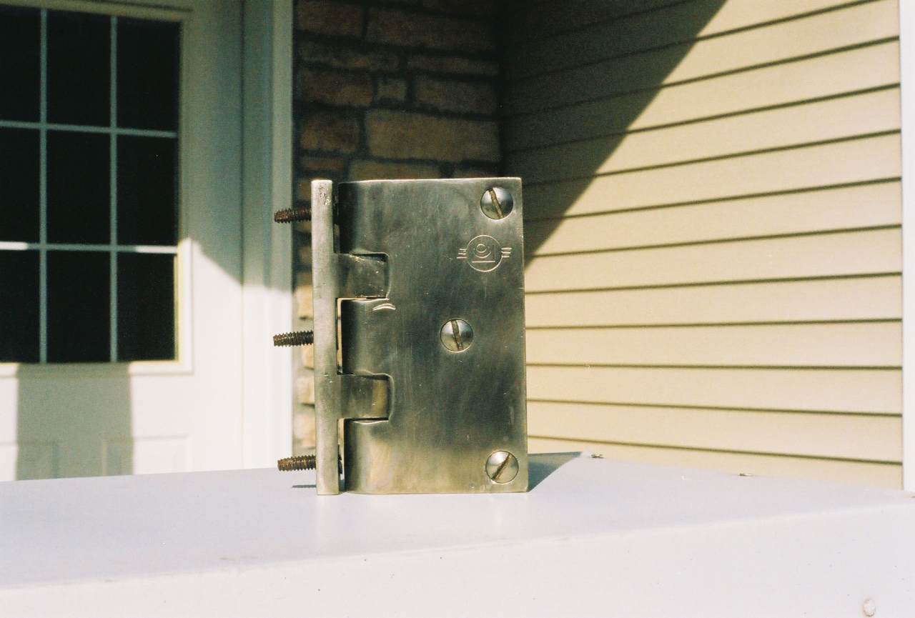 | Here's a restroom door hing, paint-stripped and polished on a wire wheel. The bracket on the left screws into the steel U-chanel inside the door frame, while the C-shaped casting on the right slips over the plymetal door. The hing pin is held captive by a set screw, which can only be accessed by removing the door. On this hing there is some obvious wear where the bracket is eating into the C-shaped casting. |
 | Everything here is brass, electro-plated with nickel. Note the double-ended screws which hold the door are actually "Riv-Nuts". The right half is a regular oval-head nickel-plated brass screw. The left half is the same, except that it's a barrel threaded internally rather than a screw. |
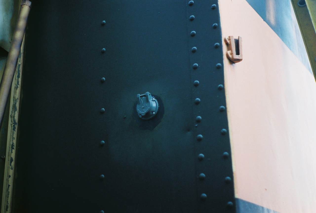
 | A partially-completed water fill cap. Still needs some parts and for the body to be removed from the car and reworked as well. |
Before too long, however, I switched to working on the car itself because the weather was so nice.
 | First, I finished the electrical conduit to the new dining room outlet, pulled the wires, and closed up the underside junction box. That's one piece of transformer-mounting prep work done. I still need to buy a GFCI outlet and make the final 'hot' connection in the electrical cabinet to have a working outlet. |
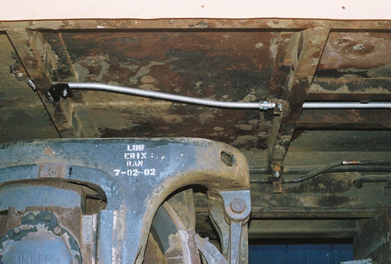
 | Second, I finished the cross-over air pipe through the center sill. I'm re-using the old HSC straight air pipe to connect the standby air compressor and toilet air to the existing water-raising system. This picture shows the brake plumbing running along the center sill. (It's all schedule 'K' hard copper.) Bottom to top, we have the brake cylinder pipe, the brake pipe, the old signal pipe, the old HSC straight air pipe, and (capped off on extreme right) the reservoir pipe. The dining room once had independent steam heat loops on each side. That nice hole in the center sill was a feeder off the steam pipe to the left-side loop. At some point it was simplified by slaving the left side off the right - that's the insulated pair in the lower foreground. The capped-off reservoir line once fed the sanding equipment. My new cross-over pipe through the center sill connects the water-raising air system to the old HSC pipe, which will connect (left) to a stand-by air compressor and (right) supply control air to the Microphore toilets. These joints are silver-soldered per Amtrak requirements. The old signal pipe may become the Amtrak MR trainline. |
That's two more items finished in preparation for hanging the transformers!
So, when am I going to get them hung? Good question. I've been thinking I might want to hire someone to engineer the mounting rails (useful for running on Amtrak and/or defending a mechanical failure in a lawsuit) and that means waiting until I fix my finances. In the meantime, I can run its conduit above the brake valves and through the water fill shroud - which means an opportunity to clean dirt out of corners, remove old head-knockers (I mean mounting brackets,) and start analyzing what needs to be fixed in the water supply.
Once the transformers are hung, I still can't hook them up. I have heard - and the more I consider it, it's probably true - that the breaker panels in the electrical cabinet must be enclosed on all sides. Mine only came with front panels, and I worry about children touching the 480v or me dropping screws into bad places.
I've also gotten back into restroom disassembly. (No longer too sick of it to touch it.) It's still very tedious work getting every stuck screw out, so that I can re-use the metal pieces on new plymetal.
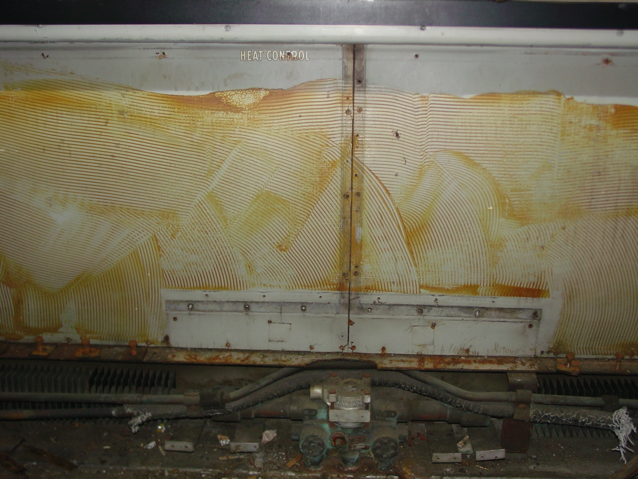
 | I have conquered the last bit of ceiling, where the air conditioning equipment juts out over the coach section. Speaking of which, that plymetal is in dismal condition! The entire thing is one mass of rot - which got me thinking about water sources again. It doesn't seem to be coming in the roof - if that were true, I would expect the tar-covered masonite lining the A/C compartment to show some sign of damage. Restroom humidity is a possibility, but plymetal closer to that source was in better condition. Was the condensate drain plugged, or water condensing on the bottom of the drain pain? Maybe... Or, (never thought of this before,) was there a leak in the steam piping? |
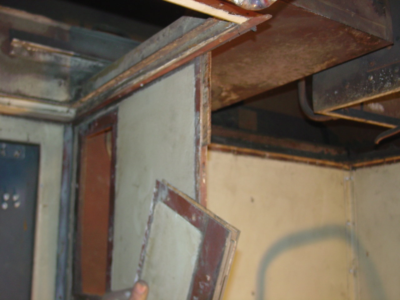
 | This shows how that ceiling was mounted. On the right, the usual L-channel secured to the wall, the ceiling secured to the L-channel, and a batten strip over the top. The partial bulkhead wall is more interesting. It's a large L-channel bolted to each wall. First the bulkhead plymetal was fastened to it, hanging over a bit at the bottom. Then the ceiling was fastened. This time a wider batten strip with two rows of screw holes was used - one row for each piece of plywood. Of course, there was the fabric tape separating everything to minimize body squeeks. Note the bolts in the bulkhead which follow the coach ceiling profile. |
 | I've gotten the aluminum panel off the men's restroom side wall. It is actually three pieces, with edges bent into the window opening, joined by spot-welding to some backing strips. Underneath, there are 1/4" Masonite furring strips on each Z-channel joist, with cloth tape over the top. Note the gussets topping the joists, the outlet and mirror light electrical boxes, and the horizontal wires security the insulation. The piece below the window is 1/4" Masonite - it was covered by the stainless wainscoting, while the end wall is all aluminum sheet. |
 | Here's the inside of the men's restroom side wall. Note the 1/8" plates spot-welded on where ever things would be screwed in, and on the joints pieces. (Gee, they got that one on the lower right in the completely wrong spot!) On the exposed side the spot welds were probably filled with bondo. The sharp-eyed could explain every detail on the back. The window, mirror, and outlet are easy. The screw line along the bottom marks the top of the stainless wainscotting. There is a corner hand grab at the right near the outlet. I can't explain the two screw plates below the mirror, or that horizontal plate above the window/beside the mirror. |
Here's something interesting Amtrak buffs might enjoy: Amtrak's paint job inside the restrooms was applied with a paint brush - not sprayed as in the rest of the car. I've been close enough to see brush marks everywhere.
 | Something I did a couple months ago - but forgot to report - was installing the A-end marker light sockets. The wires were run and the sockets had been worked over, I just had to strip and POR-15 the end sheet, chase the screw-hole threads with a tap, and caulk while installing. The circuit still needs to be converted from 120vac to 12vdc by pulling a dedicated return (-) wire - Amtrak requires the marker lights have battery backup. |
I removed the bottom shroud off one water fill, to check that I could run transformer conduit through it. While there, I also took a look at the water reservoirs and plumbing (never had before.)
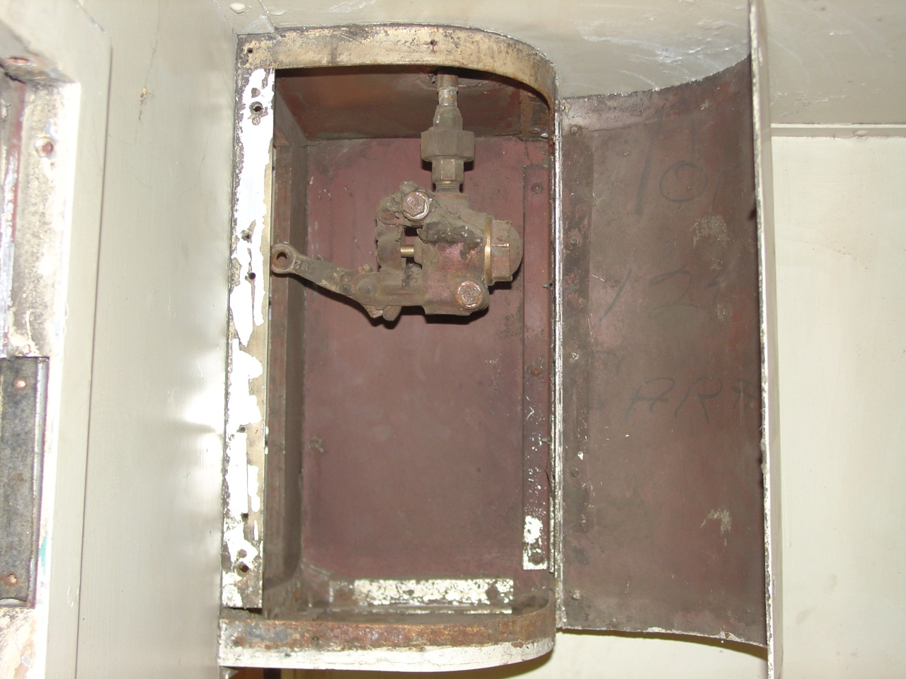
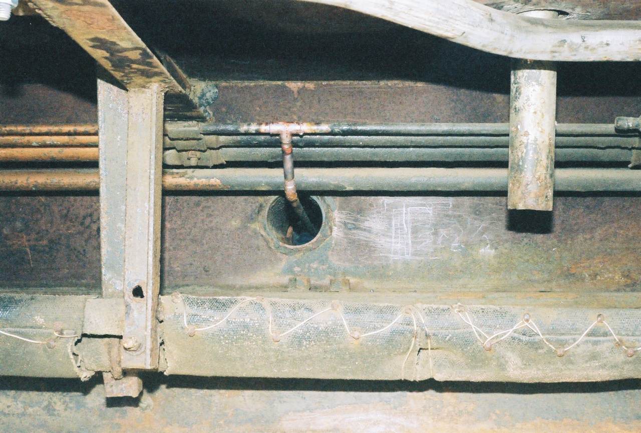
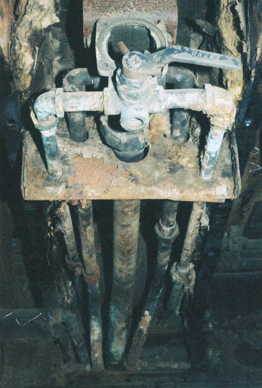 | Here's the water fill plumbing after removing the lower half of the shroud and the insulation. The water fill cap (see picture above) bolts on over that big hole. The big central pipe goes from there to the reservoir. The upper pipes on either side are the steam heat loop, to prevent freeze-ups in the winter time. The valve is a three-way cock. Handle up, it connects the two pipes allowing air tapped off the brake system to pressurize the tanks, and locks the fill cap shut. Handle down as shown, it vents the tanks to atmosphere out the bottom and the fill cap can be opened. The cock is of the lapped, conical style. I'll have to remove it and re-lap it. The fill cap bolt holes also need fixing. |
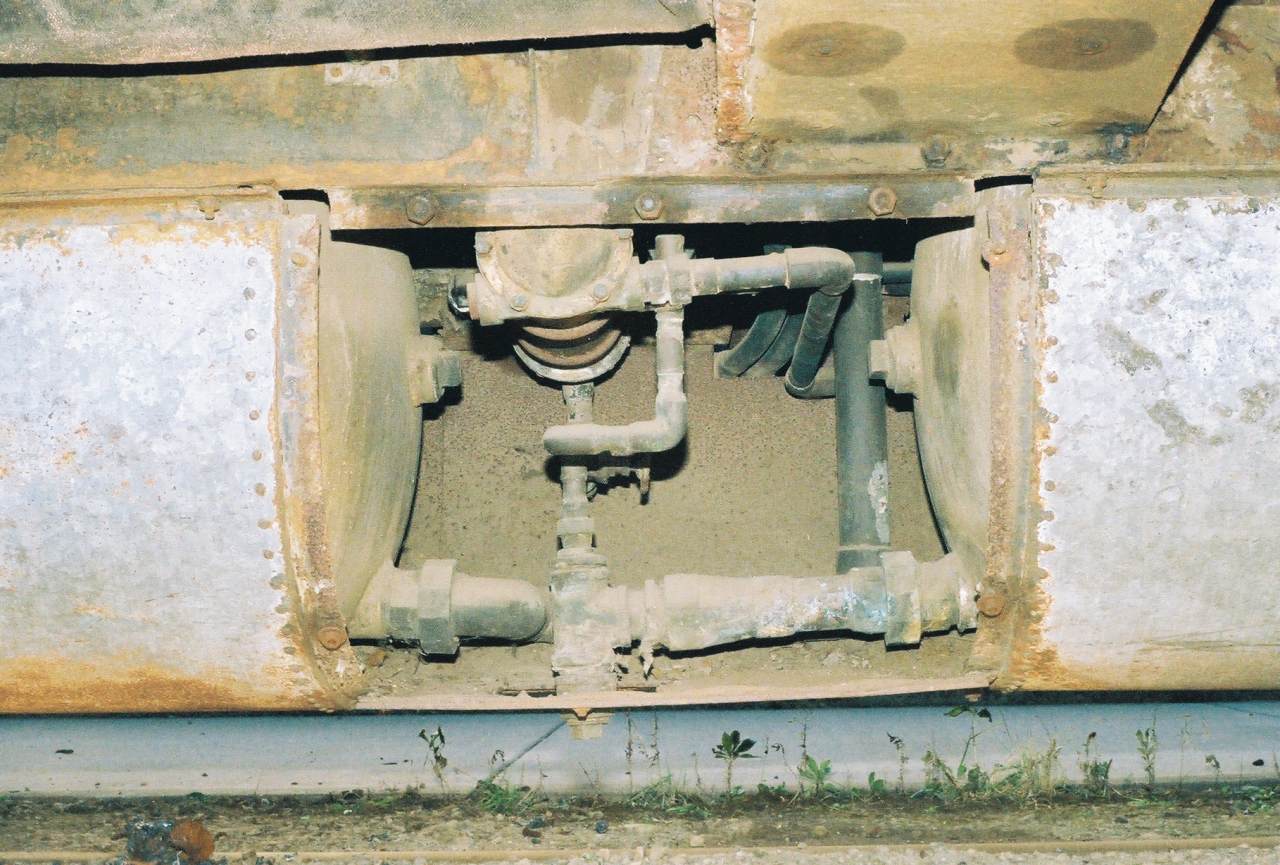 | The water reservoirs, behind the service panel. 1146 has a pair of 200 gallon stainless tanks, for 400 gallons total. (Coaches usually only have one such tank.) Hurrah! They really are stainless! Pullman used porcelain-lined mild steel and those just don't last. Less work for me! The vertical big pipe is the line from the water fills. It connects to each reservoir, a drain valve at center - partly obscured - and the smaller water pipes into the car. That round device is the water heater (steam-powered.) The cold water line jogs around it. There are shutoff and check valves before the water heater. The two curved pipes notched into the opposite side's access cover were added later - they slave the dining room's left side heaters off the right side's regulator valve. |
The last Sunday in October I spent underneath making fire. I had to change the drain pipe on the kitchen fold-down lavatory to match the trap, got the extension pipe from the old soldered to the new. I also cut down conduit that interferes with planned conduit to the transformers.
A bit of research: There are three ways to restore the restroom exhaust fans. Service the existing 32vdc units and add transformer/rectifier power supplies like I did in the kitchen for $60 each, replace the motors with 120vac units, or replace the entire fans with 120vac units. These Dayton 9" ring exhaust fans from Grainger (look at the bottom) seem very close and cost about the same. Because these fans aren't visible, why not?
I was also talking to Dad about restroom lavatory hot water. I'm intrigued by the idea of using little instantaneous hot water units under each sink. The benefits would be simplified plumbing, less heat tape, and no waiting for the hot water to arrive from the water heater. The cost would be buying multiple heaters (ballpark $250 each) and providing for peak electric consumption of 3 to 5 kw. The variables are consumption (Dad says .5 gpm is a rule of thumb) and "Delta T" - the temperature difference between the cold water and the hot water. The Architecture & Engineering firm he works for typically specifies units from Chronomite or from EEMAX. My puzzle to solve is what the minimum cold water temperature will be, factoring in freeze protection, and what I'll do for kitchen hot water.
I got a little work done in November. I contacted one firm that does passenger car structural engineering (about the collision posts and transformer mounting) and basically learned I can't afford them until I get my finances fixed. A friend gave me a couple other leads I still need to follow up on.
I did get the opportunity to guess at major expenditure dates by extrapolating my finances into the future. It looks like asbestos abatement of the coach section and restrooms will happen in August of 2007. Engineering (based on the quote I got) could follow six to nine months later. Next after that would be repair/replacement of the overhead blower/heat exchanger unit - in late 2008 or early 2009. (Yes, I've been wondering if I should lower my standards a bit. After all, I'm planning to operate it in tourist/historic service. ...but then I remind myself that it's always cheapest to do things right the first time, and cutting corners now will forever preclude the possibility of running behind Amtrak.)
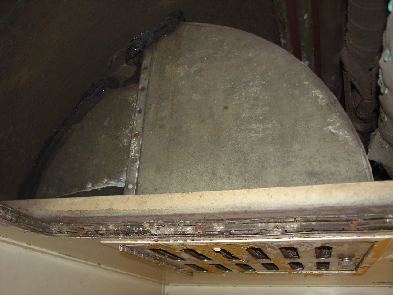
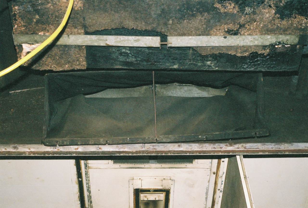 | I spent some time trying to disconnect the existing heat exchanger. This is the rubberized fabric boot connecting its output to the ductwork. Here the boot is detached from the heat exchanger, and hanging from the ductwork. This end is sewn around a rectangular wire frame. The top fits into a flange, the sides are held by clips with wing nuts, and the bottom is held by several wing nuts on bolts which can swing down out of the way. |
 | Here's how the air diffuser/light fixture opens. The "screws" actually have a leg on each side and seat in a spring clip with a quarter-turn. Those electrical cables have melted/cracked insultation, and are the reason I never did the coach ceiling lights. |
 | The air diffuser/light fixture is completely open. That top batten strip secures the top of the boot to the ductwork. The other three sides had batten strips screwed into the vertical bulkhead wall from the outside. The "ductwork" is just sheet metal bent and screwed to the inside of the roof, with tarred joints. (Some problems noted with those screws and joints. Hmmm.) |
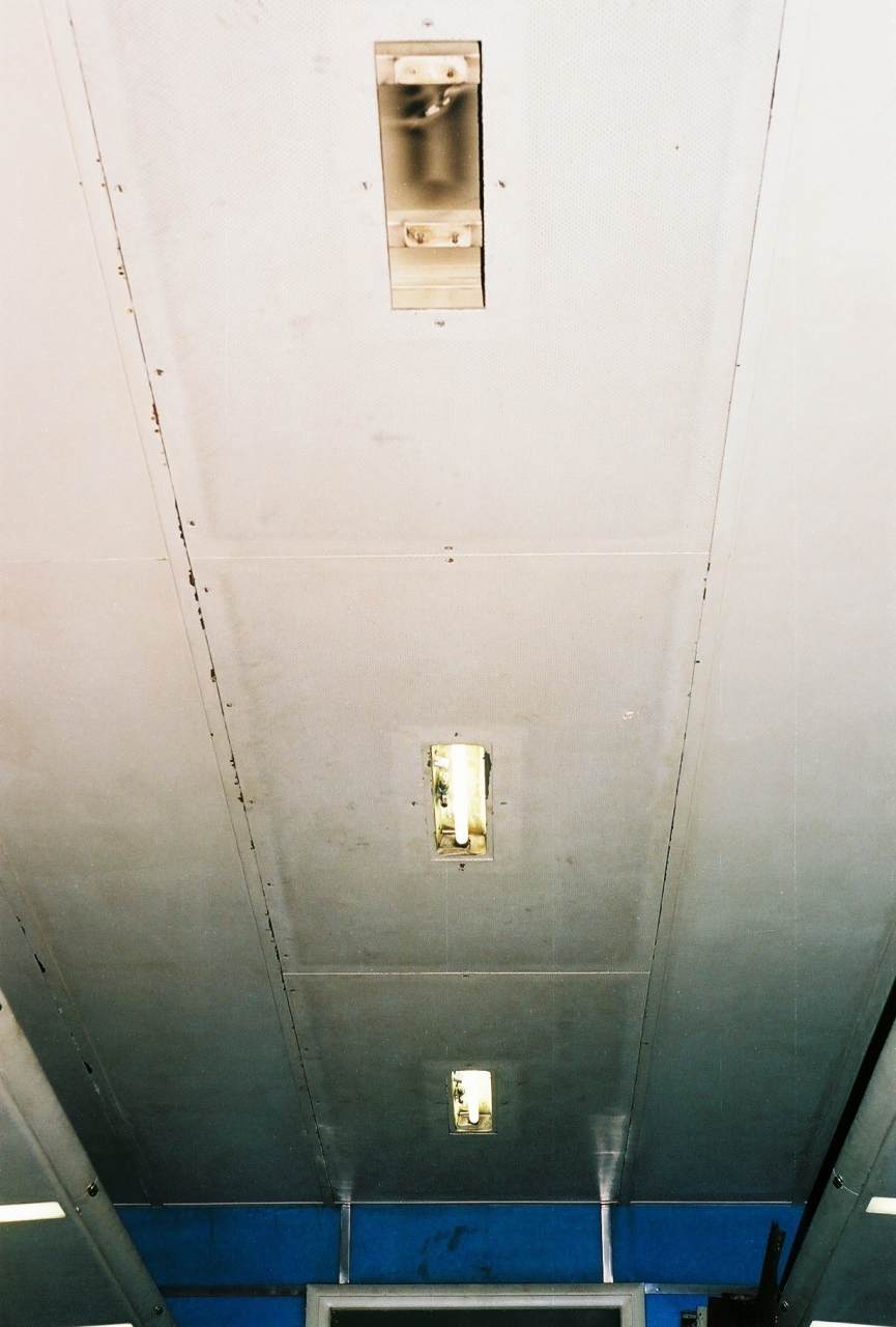 | I'd never gotten my head that far up into the ductwork before. When I did, I found the electrical conduit and junction boxes running along the left inside of the duct, out of sight from below. Cool! Believing good work lighting is important, I was spent a day of vacation re-wiring the ceiling lights. Like other ceiling lights, I ran five 14 AWG, 2 KV Exane stranded copper wires. Color codes are Black (120vac hot), White (120vac neutral), Green (ground), Blue (12vdc +), and unmarked (12vdc -). Why run a ground wire? Fluorescent ballasts for these T8-18 lights use the ground as part of the circuit. A friend and I got wires run the full length, and two lights in. Wire joints are soldered and sealed in heat-shrink tubing with the end folded over and taped. The branch to the fixture is five wires in two layers of heat-shrink tubing. Having just those two lights working is a marked improvement. |
 | A couple High School-aged museum members were there that day, and they helped by removing the stainless wainscotting and rubber floor tile from the women's restroom. Progress! (The masonite scraps are because of a draft of cold air wafting up through the poop holes. |
Finished the coach ceiling lights one Sunday afternoon. Otherwise, I didn't have time to work on it.