Last July, when I asked about cherry-picking W8-28# beams, the good folks at Linders Specialty Co. recommended West Central Steel in Willmar, MN. Sure enough, when I call 'Jeff', he said to cut out a sample or take good measurements, and bring it over. They'd be happy to dig through their inventory and, if they can find a match, cut off what I need. Jeff also commented that wide-flange beams and C-channels are some of the sloppiest steel products out there, varying widely in dimension - even within the same beam. Some aren't even square in cross-section.
Then last December, Amtrak Ok'd using the splice which Starfire engineered, despite the additional pitting near the hand brake, or replacing the entire post - my choice.
This week, in a conversation with my local car contractor/Amtrak inspector, he suggested the engineer might approve slicing the W8-28# beam I bought down the middle, and welding it back together so that its exactly eight inches wide. Not a bad idea - a beam's two critical areas are the face under tension, and the face under compression. Everything in the middle exists only to keep them spaced properly. That's why it's OK to drill a hole in the web of a beam, but dangerous to nick, cut or weld either face.
What I may do is remove 1/2" from the BR (non-hand brake) collision post, at the splice location. That allows me to monitor for shift or droop, and yields the sample I need for cherry-picking replacement material in Willmar. If I score, great! If not, I've got plans B and C.
This year's RPCA convention was in Pueblo, Colorado. Some highlights relevant to 1146:
Any private car owners with their own reporting mark should check and update their contact info in FindUs.Rail, making sure to assign it to the Bad Order Disposition, Car Repair Billing, Customer Service, Damaged Defective Car Tracking, and Umler/EMIS categories.
Do not put the car's ledger value in Umler/EMIS. DDCTS (Damaged Defective Car Tracking System) uses the ledger value to decide whether wreck damage exceeds the car value, to automatically authorize scrapping. Setting the ledger value to zero prevents automatic scrap authorization. Also, the rate indicator should be 6 "Zero-Rated Private".
Those with their own reporting marks should not allow others to use, without sufficient protection such as a contract or requiring insurance. This is because the mark owner has legal liability for the cars marked.
If there is no valid air date, the computer may assign Mechanical Restriction X "AAR Interchange Restriction" reason B "Due to Air Brakes". This is sufficient cause for any railroad to refuse to accept the car in interchange.
COT&S Stencils are superceded by the Air Brake Test data in Umler/EMIS. If present, they should match Umler/EMIS.
If the COT&S is not being done because the car is inactive (such as being in the repair shop,) be sure to set the status code to I "Inactive". This is insurance against fines.
Railroads have requested (but do not require) the reporting mark and car number be displayed on each end of the car, on both sides - all four corners. This is for their crew's convenience.
Last January it was reported that Amtrak is updating documents for PVs. The current documents date from the 1980's - see NRPC-Amtrak Standards and Maintenance Procedures for samples, such as car clearance diagrams, SMP 28603, and the PC-1 form. This revision is prompted by upcoming retirements of experience people and the need to update references to materials, vendors and other documents. The updated SMP should be published in early 2nd quarter of this year.
Private cars used in Amtrak service should be maintained to the specs that were in force when the car was constructed. Major modifications (such as adding an open platform) should be engineered to current standards.
Amtrak says that oil-bath roller bearings on wheelsets like 1146's will not be accepted, starting January 1st, 2020. That prompted questions about replacement options. Two good wheelset builders for passenger cars are NRE Wheel Works Inc. in Milwaukee, WI and ORX in Tipton, PA.
Axle-driven generators, whether belt- or Spicer-driven, will not be accepted starting January 1st, 2013.
UC-type brake systems will not be accepted starting January 1st, 2012.
Amtrak is not accepting any new Private Cars with propane. (The classic Waukesha 100 lb bottles are not DOT approved, and must be removed to be filled by weight.) Any existing propane tanks should be under the car, properly enclosed, and plumbed with metalic piping.
No bad paint jobs on Private Cars please. That reflects poorly on Amtrak.
Regarding freight car brake valves on passenger cars. The current freight car code of tests does not account for the relay valves and other air uses found in passenger cars. This will be addressed in the updated Amtrak SMP. Note that freight car brakes in passenger trains are subject to operational constraints because they do not support graduated release.
Amtrak will need to know the correct brake cylinder pressure in full service and in emergency. The calculation is straight-forward, but requires accurate weighing of the car at each truck.
Only electrical items should be stored in the electrical locker. Anything else is a fire hazard or an impediment to use/maintenance.
Amtrak requires at least one conductor (emergency) brake valve be located inside the car.
The current air brake codes of tests require brake cylinder pressure test fittings. These should be present on the car.
Starting in 2013, Amtrak will require the 27-point communications line be present.
Timken AP-EE journal bearings will disappear in approximately two years, as the Heritage fleet is replaced by new cars.
Michael Burshtin from Amtrak also recommended upgrading to equipment which Amtrak stocks, so that defective wheelsets can be (relatively) quickly changed out. For example, new cars have been ordered to replace the Heritage fleet and will arrive in the next couple years. Once the Heritage fleet is retired, Amtrak will no longer need to stock 36" tread-brake wheelsets with 5.5x10 AP-EE bearings. One Amtrak car inspector says they've standardized on class-B (tread-brake) wheels and Timken AP-G bearings for new equipment. Since wheels for small-diameter axles are scarce, vendors like CBX, NRE or ORX can press Amtrak wheels onto a used locomotive axle, and machine it to accept AP-G bearings on 5.5x10 centers. The result would be a custom wheelset (not stocked) with standard components, which would fit in the AP-EE adapter boxes in a 5.5x10 truck, costing around $5000. In an emergency situation, it might take a week to replace, rather than several months.
Starting January 1st 2011, NWRAIL is not selling new air conditioning systems for use with R22, which is a CFC. All now use R422B.
Dynamic Metals, LLC is a relatively new vendor to watch. They purchased window suppliers J.T. Nelson and R.A. Jackson, and seem to be the heir-apparent for Adlake window sash assemblies.
One car owner who works for a short line demonstrated a GPS motor fleet tracking solution from Discrete Wireless. After placing a 12-volt DC supply, antenna, and their GPS unit in the rolling stock, their web site allows complete reporting on location, time & direction of movement, and velocity. Qualcomm was mentioned as another possible vendor.
A sign company spoke on the option of using vinyl wraps instead of, or over, paint. These wraps are frequently seen on city busses and light rail. In theory one could do the body work and primer, and then wrap with printed vinyl. I gathered that wrapping costs as much or a bit less than a good polyurethane paint, but has about half the life expectancy. For someone leasing their car to a customer who wants their own image on the car, this is an excellent option.
| Found this interesting shot that appears to be Amtrak 8400 or 8401 leaving Chicago Union Station southbound behind a GM&O E7 and one of the original Burlington home-built dome cars on April 6th, 1973. Posted by Gerard J. Putz on his WordPress blog under "Milwaukee Road". |
1146 now has an Amtrak 800-thousand number: 800959. These are assigned to privately owned cars which operate in Amtrak trains. For a car being restored/upgraded like 1146, it serves mostly to keep engineering, approvals, inspections and communications together in the same file. It took a while to figure out how to get the number. I had the opportunity to speak to Amtrak people at the RPCA conference and learn what they needed.
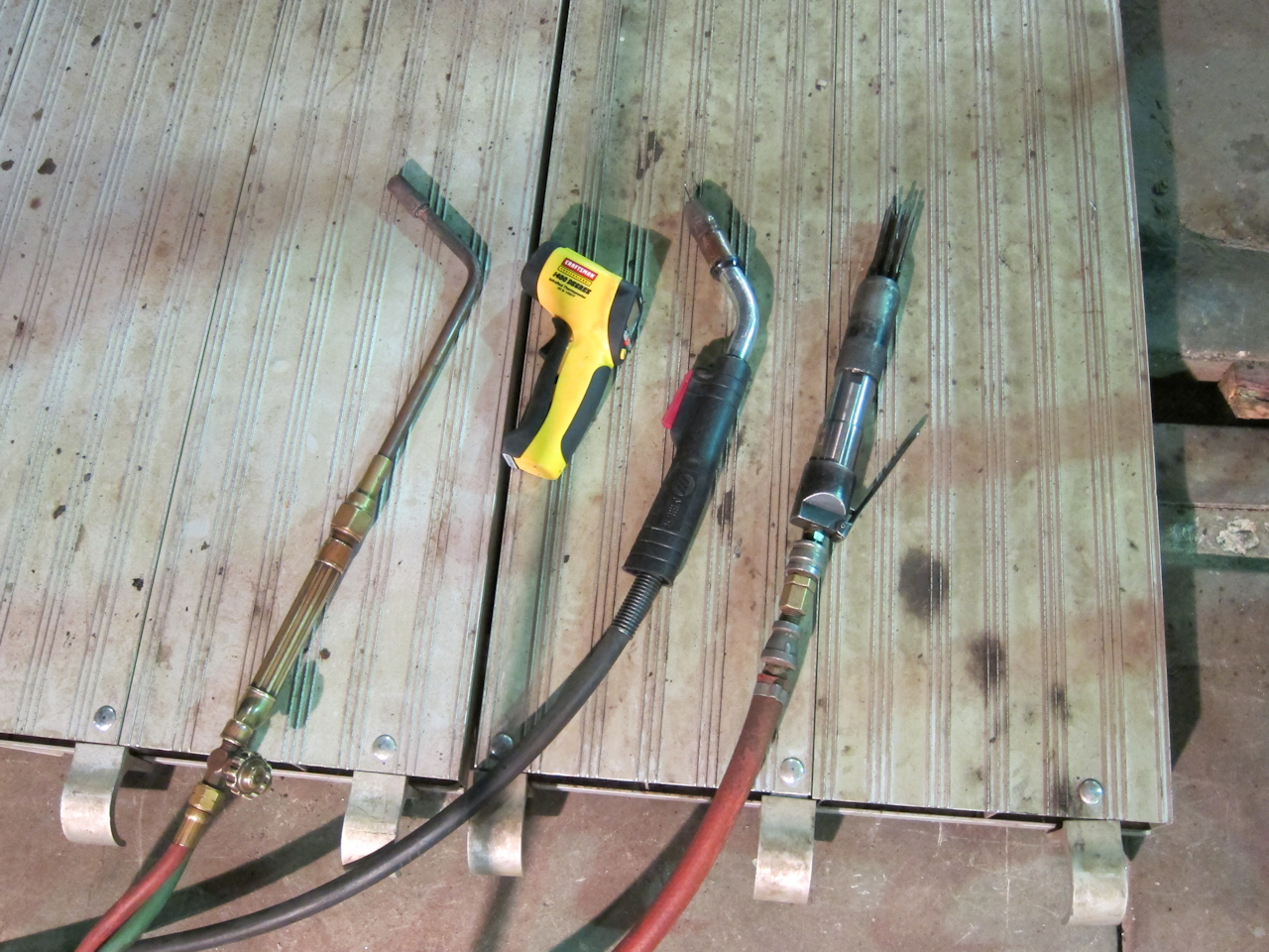
I recently bought a steel saw for fabrication work. Thought it might be interesting to compare some different cutting technologies:
A couple friends wrote after I posted the tool comparison above. One has an Evolution Power Tools "Rage 3" compound miter. He bought it to cut 3/32" sheet strip into short lengths. His conclusion is that its neat to have a saw that cuts steel, and with proper precautions it can be done safely. However the saw might work better with longer lengths and/or thicker stock that he was cutting. His sources were Ron's Home & Hardware for the saw, and BuyWELD.com for the stand. Another friend wrote to contribute this interesting link: DualSaw QuadForce.
The museum plans to paint the vestibules in two GN coaches this winter. That sounded like an opportunity to test a color match, so I took in the coupon I'd removed from the vestibule last August.
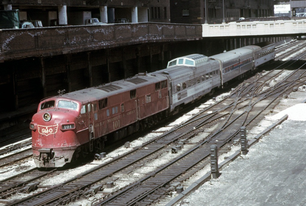
 | After scrubbing down to the oldest layer with soap, Scotch Brite and running water, I asked my local Dupont Imron dealer (National Coatings and Supplies at 1166 S. Robert St.) to try matching a color sample from the vestibule interior, which is a tan with a subtle rose tint. He sprayed a clear gloss on half for a better match. The test sample marked by the arrow is his final mix. At first glance, I did not see the test swatch. |
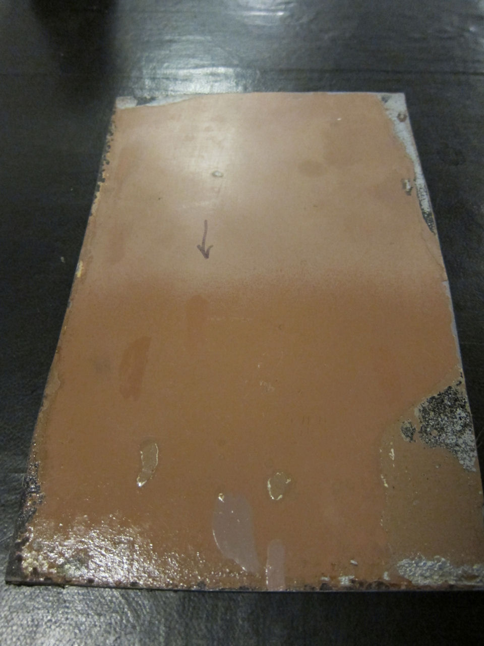
 | Another view, in mixed indoor (metal halide) and outdoor light. Interestingly, the slight color difference is more visible to the camera than the human eye - and a closer match than the GN achieved in subsequent paintings. |
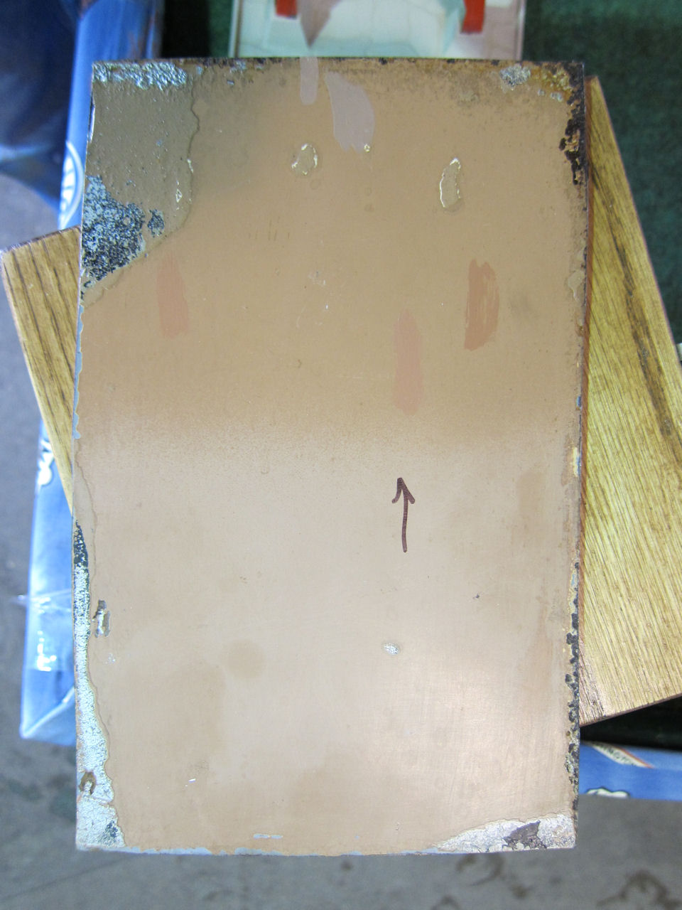
 | Outside on an overcast day, the camera picks up the slight color difference. Might be a hair too pink in color. Even the GN didn't get a 100% match in subsequent repainting - note the remnant in the upper left. |
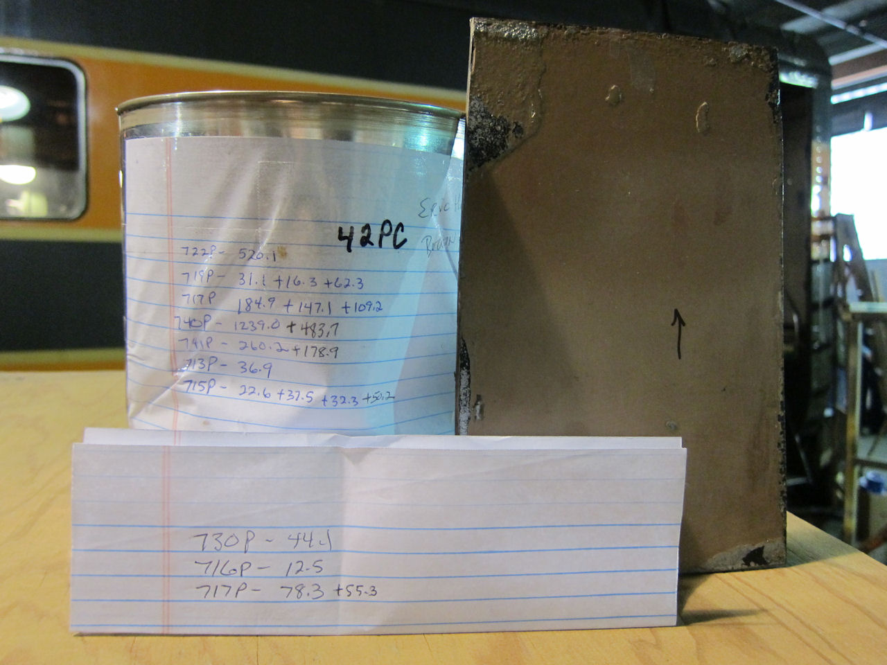 | Here's the paint can, with the jobber's mix notes. His first attempt looked too chocolaty and not rose enough in bright sunlight, so I took it back. The additional note paper shows what he changed. |
Here's the formula he came up with in Dupont Imron 3.5 HG:
| Component | Code | Quantity |
|---|---|---|
| Blue | 713P | 36.9 |
| Violet | 715P | 142.6 |
| Magenta | 716P | 12.5 |
| White | 717P | 574.8 |
| Red Oxide | 719P | 109.7 |
| Yellow Oxide | 722P | 520.1 |
| Red | 730P | 44.1 |
| Balancer | 740P | 1722.7 |
| Binder | 741P | 439.1 |
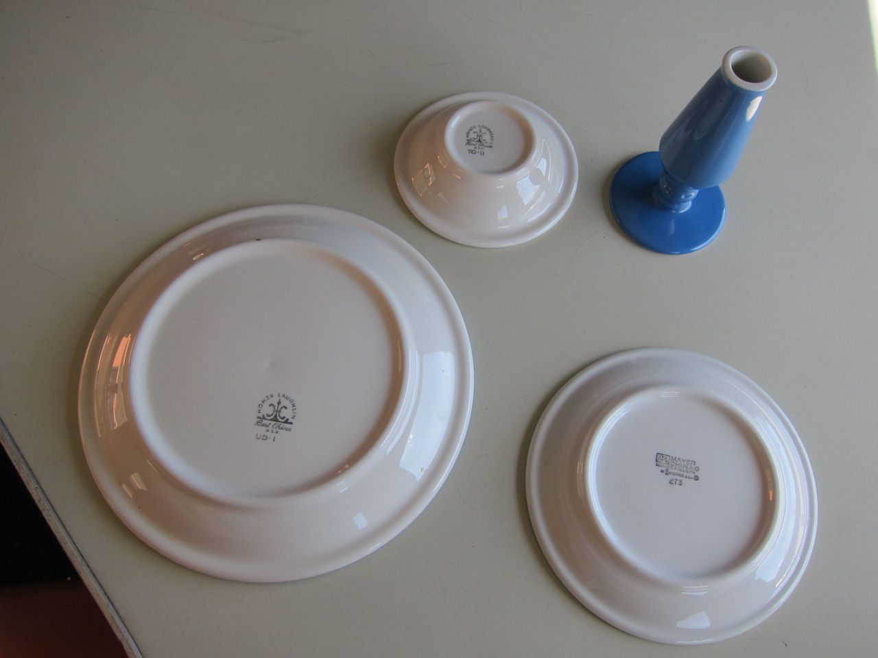
Ryan Kertis, who has helped me find several collectable GN dining car items, managed to identify two china patterns that have been used in 1146:
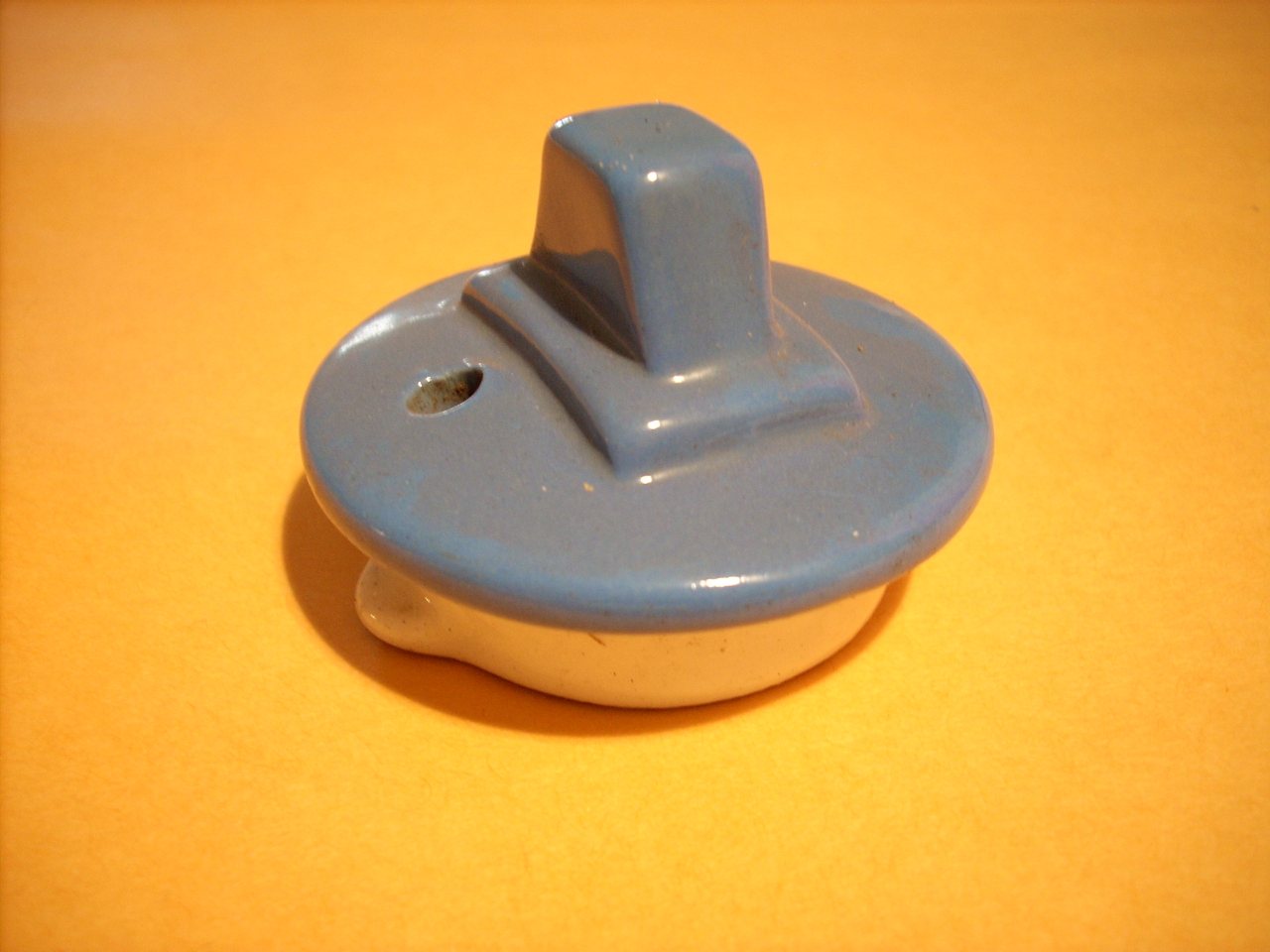 | The first is a ceramic lid which I found in 1146 years ago. According to the Restaurant Ware Collectors Network, this is a lid for a teapot, coffee pot, or creamer. They were made by Hall China, but in a custom shade for Amtrak. The pattern is known as "National", and was used from approximately 1973 until 1980. |
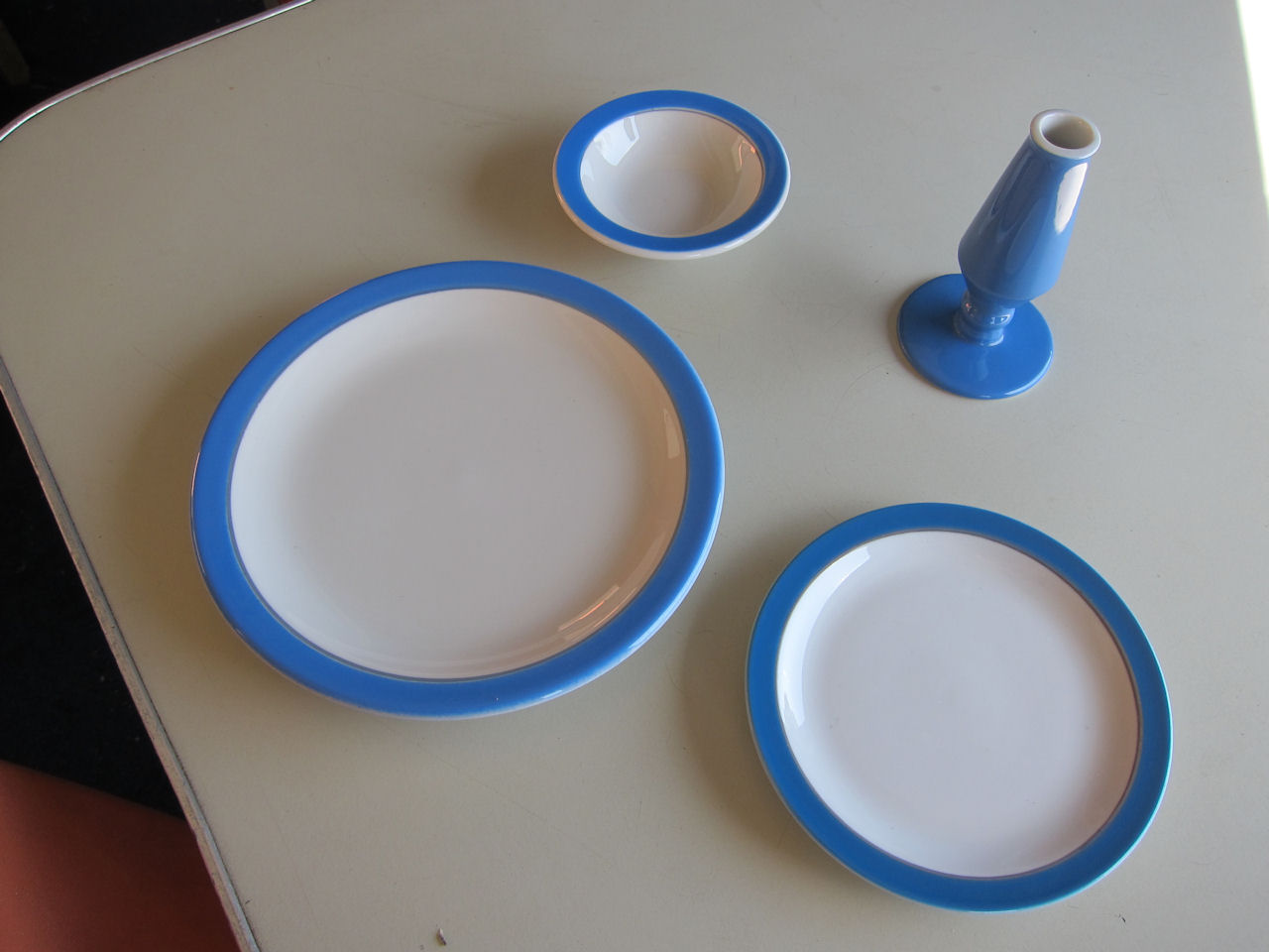
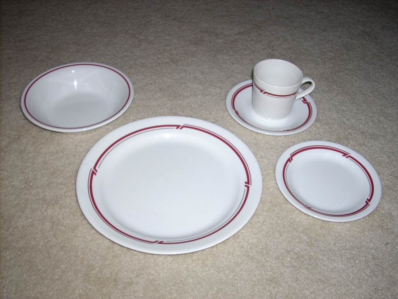 | The second is unmarked set of sixty place settings which I bought in June of 2007. According to the Restaurant Ware Collectors Network, this is known as the "Amtrak Claytor" pattern. It was made for Amtrak by Corning in 1993, and used until approximately 2006. |
Found on e-Bay: The 1977(?) edition of "Amtrak Consists" by Wayner Publications. The 8400-series diners were on the New York-Detroit Niagara Rainbow via Buffalo and Canada. 1146's Amtrak history has been updated.
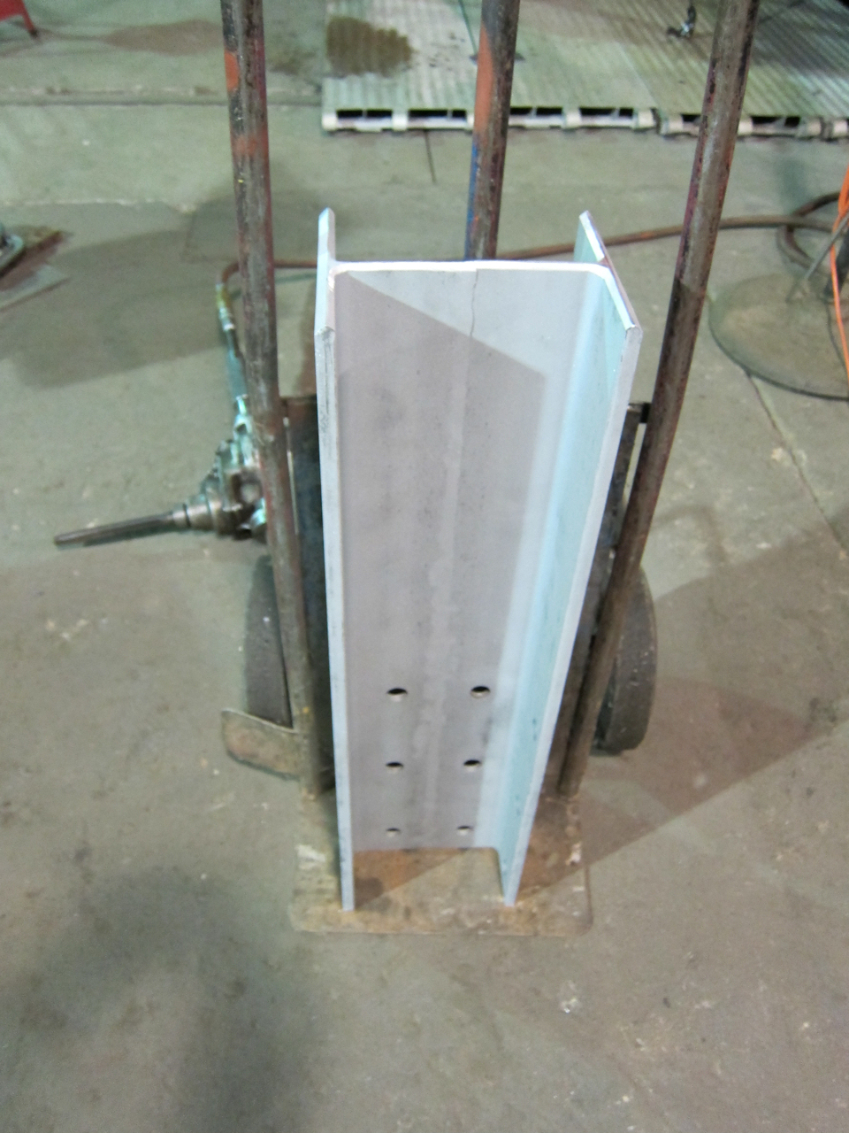
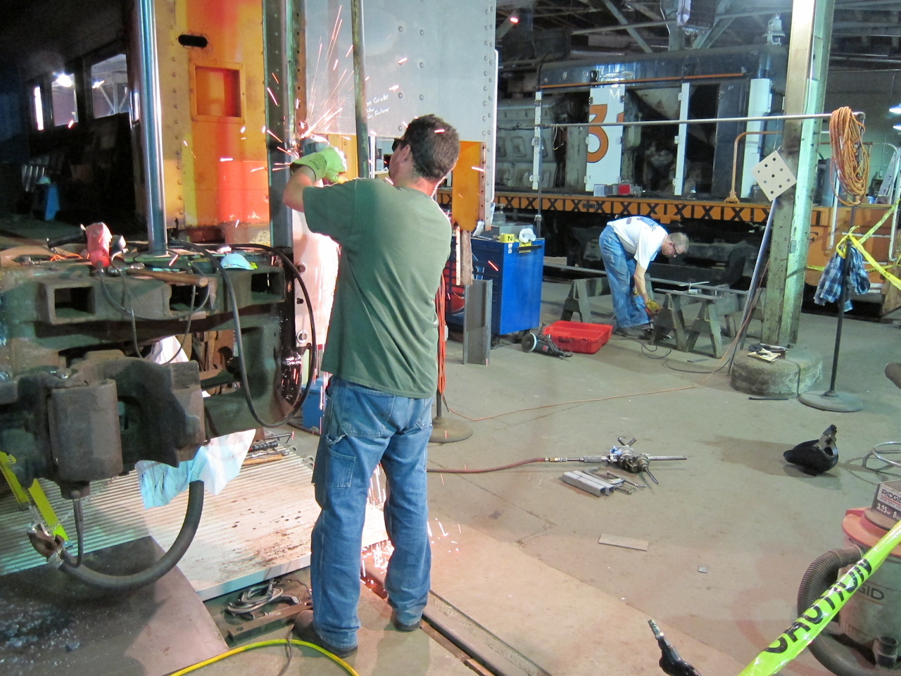
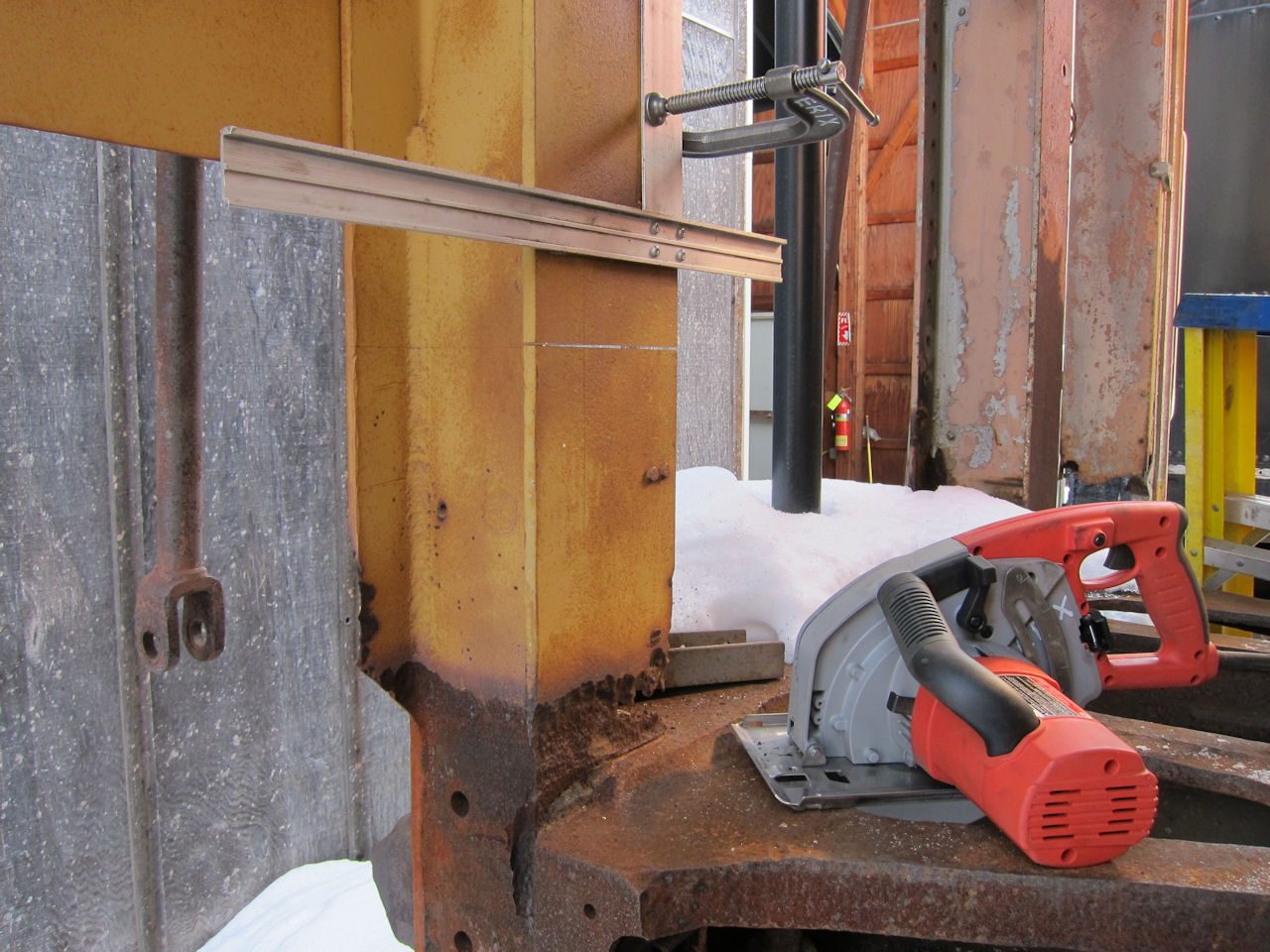 | Spring is "get busy!" time at the museum, but I since I was out in 1146 cutting a bit of steel for something else, I made what cuts I could with the steel saw to get a collision post sample. Note the drywall square used as a cutting guide. |
 | Repainting the SDP40's nose after a couple of us did the Bondo work. |
 | I did all the rear steel work: Replacing part of the end sill, putting the handrails back in their original positions, and adding the ditch lights. |
 | Here's how the SDP40's front turned out. |
 | I found a few Amtrak "National" pattern china pieces on e-Bay. |
 | Back sides. |
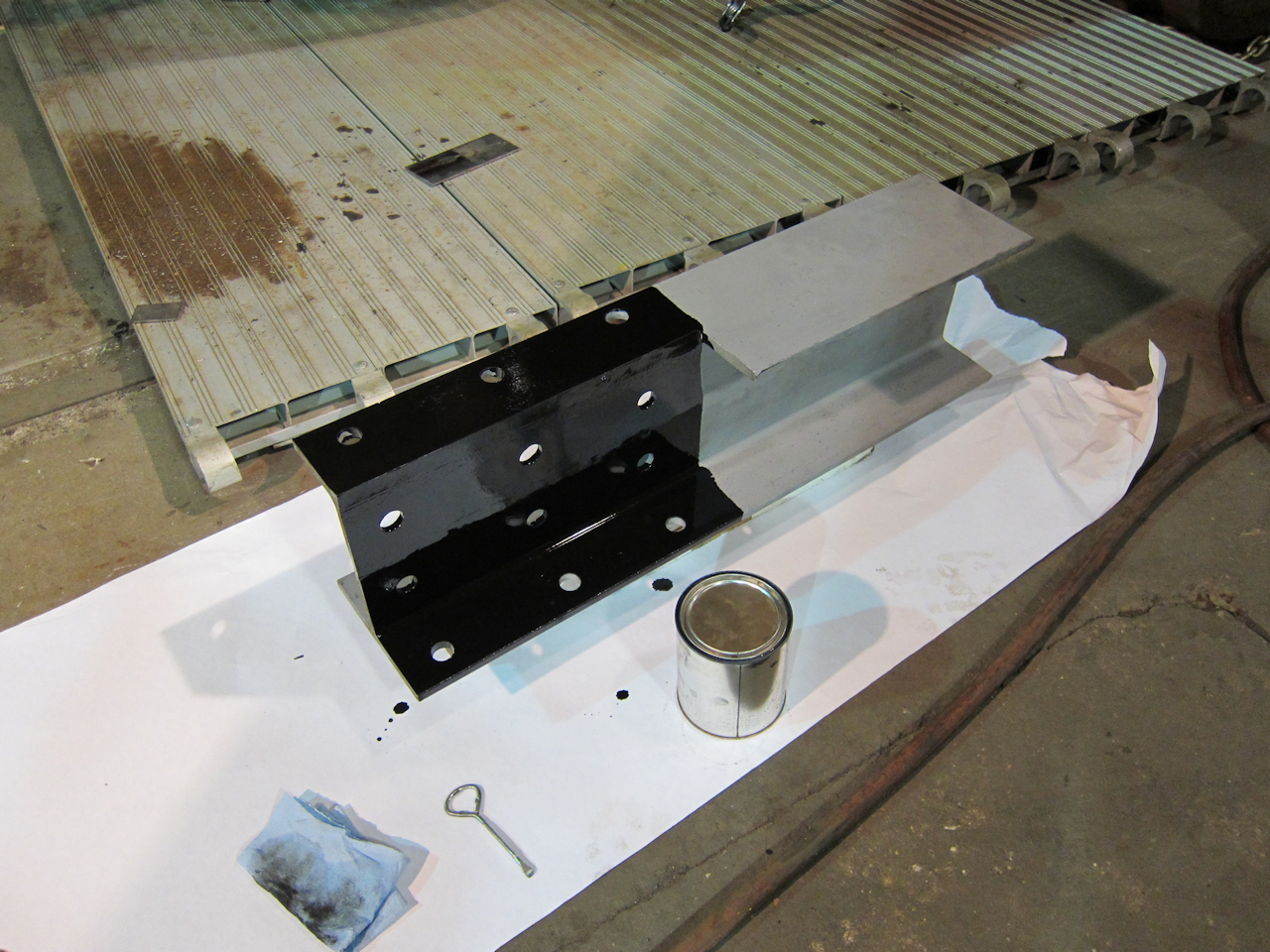
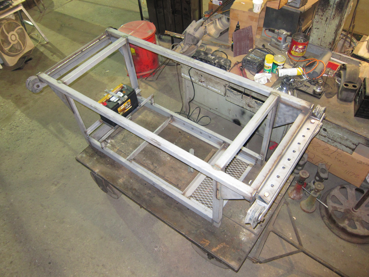 | Another museum project this spring: Fabricating a frame to hang the new Cummins generator under the concessions baggage car. I reused old Waukesha Diesel Enginator roll-out/vibration-dampening assemblies, and put them on the same centers so that the Cummins will drop in where an Enginator was. |
As a public service I've scanned Amtrak's passenger car equipment diagram book. They put this together around 1977 when the first Amfleet cars were on order but not yet delivered. This .pdf is 133 mb - 300 dpi and text-searchable.
Sometimes it pays to flirt. After using 1146's kitchen to cook for the museum's annual meeting, I stopped by a gourmet store to get needed supplies. A professional chef (she was cute!) was prepping for a demonstration. I got to asking questions, and she clued me in on the one restaurant supply wholesaler in the Twin Cities that accepts anyone's money: Hockenbergs Food Service Equipment and Supply Co. A few days later I checked them out. Excellent selection and prices, vendor catalogs, design services, and right next to Norfolk Southern's Triple Crown terminal!
Also this month, I added some period "Red River" advertising to the history section. The "Red River" was the third equipment set ordered and built by ACF in 1950, with the two "International" sets.
Amtrak issued their updated forms and instructions for privately-owned cars. The RPCA has them in a .zip file at http://www.rpca.com/pdfs/Amtrakampandforms.zip.
I found four more pieces Amtrak "National" pattern china on e-Bay.
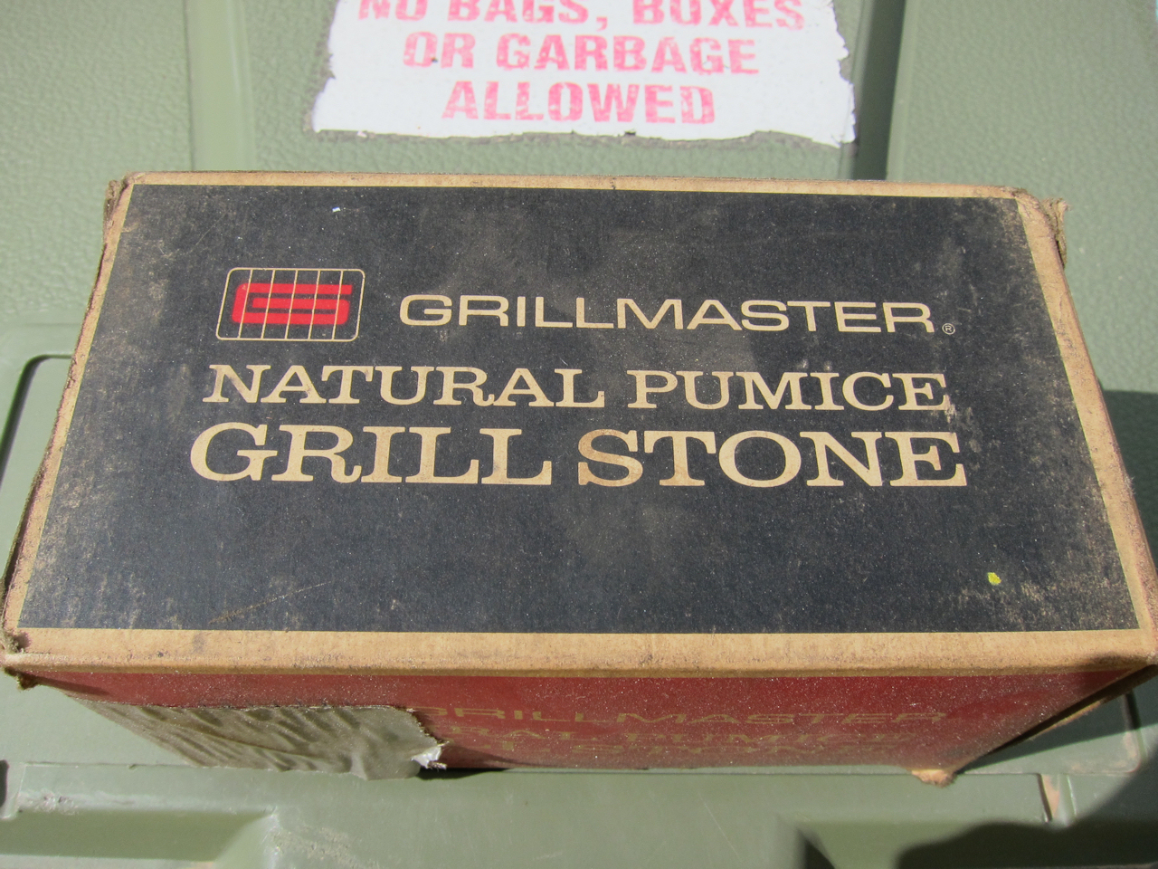
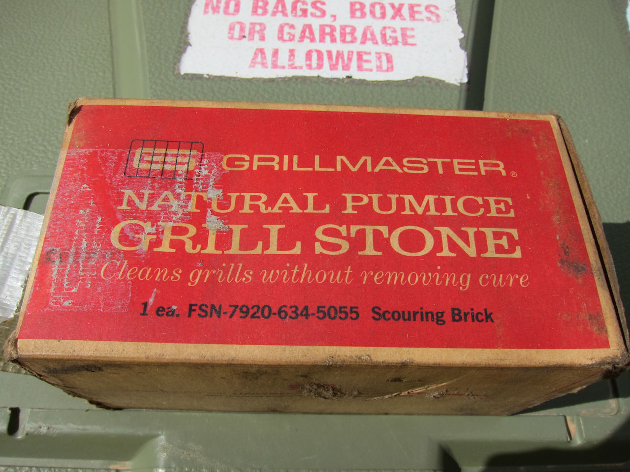
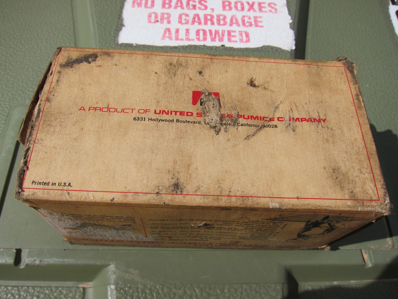
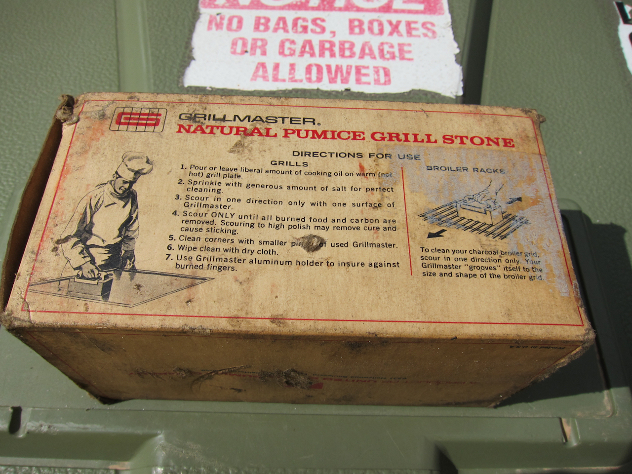
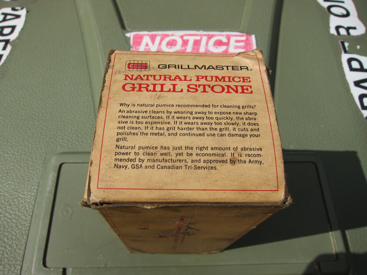
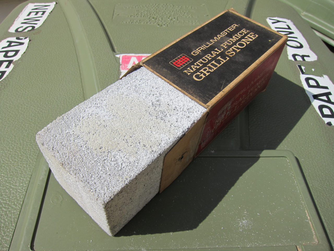
| A historically correct pumice stone for cleaning 1146's grill? Our museum warehouse man found this: A new-in-box stone which was in the baggage-turned-MOW car when they acquired it in the 80's. (Same baggage car I hung the Cummins under.) These stones are still available for purchase. | |||||
 |
 |
 |
 |
 |
 |
No time to work on 1146 - too busy doing air brake COT&S work for the museum.
I found a 1950-vintage advertising brochure for the "International" on e-Bay.
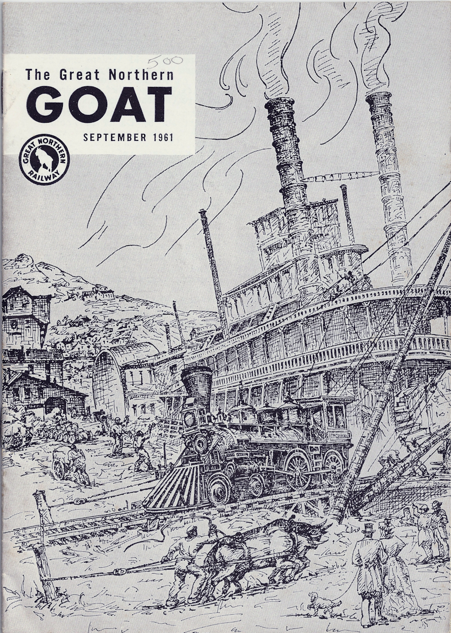 | Reader Chuck Hatler contributed this scan. It's the front cover of the front cover of the 1961 GN Goat. The line-drawn artwork depicts the William Crooks being unloaded off a steamboat at St Paul. He speculates that such artwork was used for the etched stainless "pictures" on the bulkheads on either side of the coach section ends. From his youth, he remembers seeing this image and one of the construction of the stone arch bridge in cars. |
 | Only marginally related to 1146: Advertising found at a Minneapolis light rail station. |
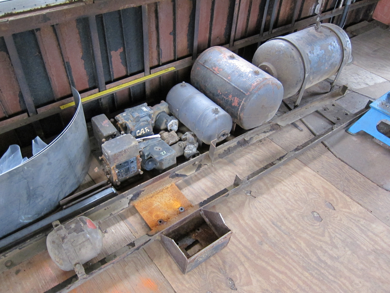
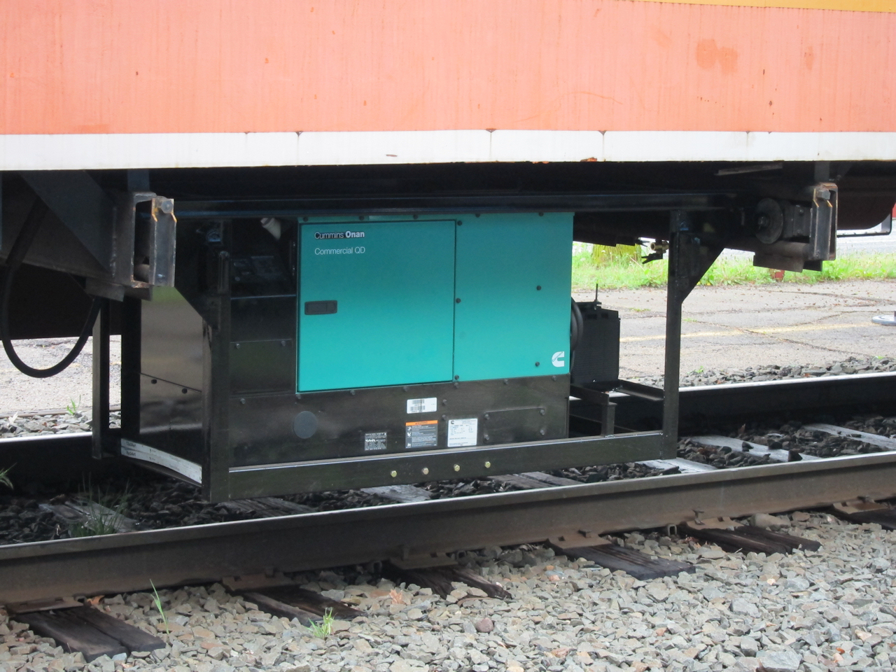 | Here's how the generator installation under the museum's baggage car worked out. Note the filters for the bottom air intake, to protect from ballast and dust. Please note I didn't install the roll-out rails - they're a couple inches too low. |
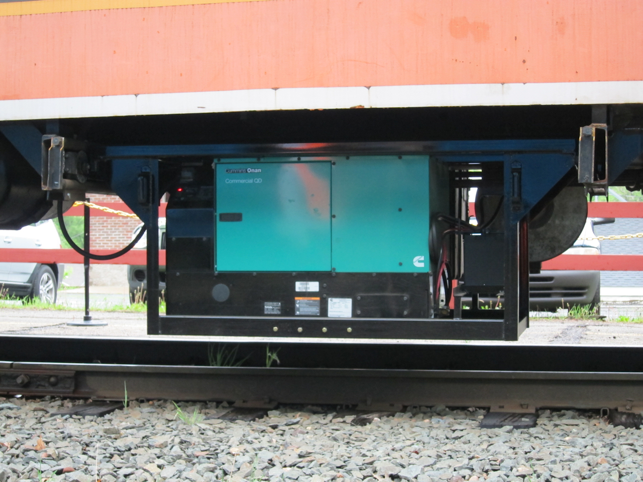 | Front/right: Starting battery and a semi trailer aluminum diesel fuel tank hung on the opposite side. |
On May 19th, I took a day off and drove to West Central Steel in Willmar, collision post sample in hand. It turns out they are a whole saler, and supply several of the steel retailers in Minneapolis, including North Second Street Steel where I bought the new beam. We compared my sample with every W8x28 in their inventory. Every single one was wrong - and identical to my new one. It must be the steel mill they're coming from. I came home more educated but empty-handed.
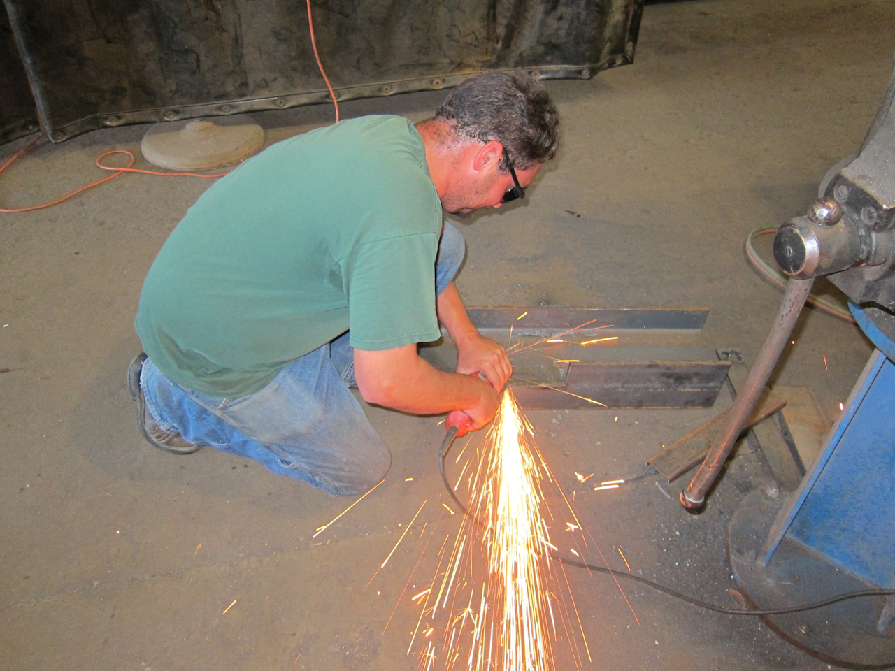
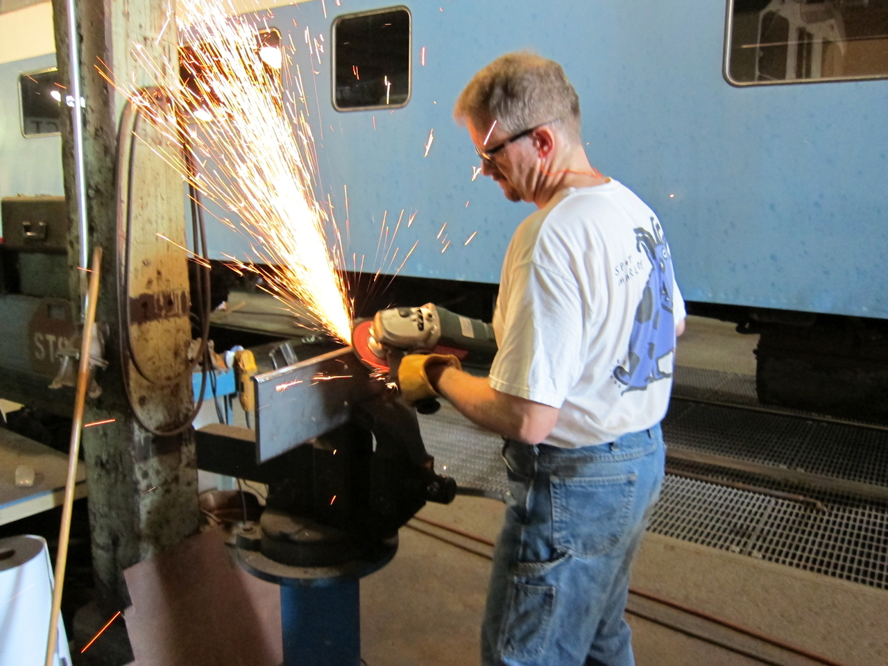
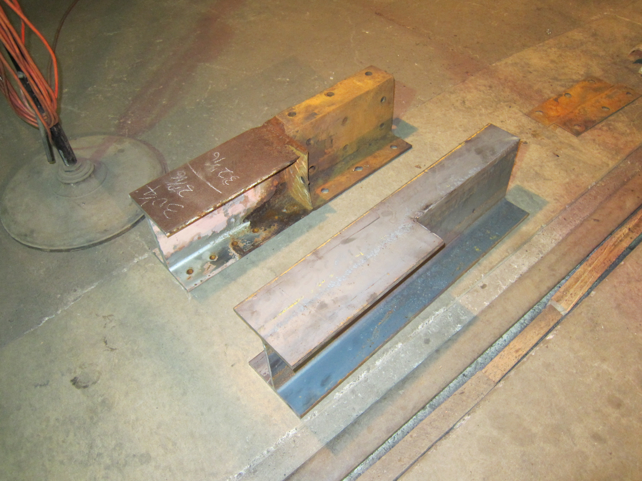
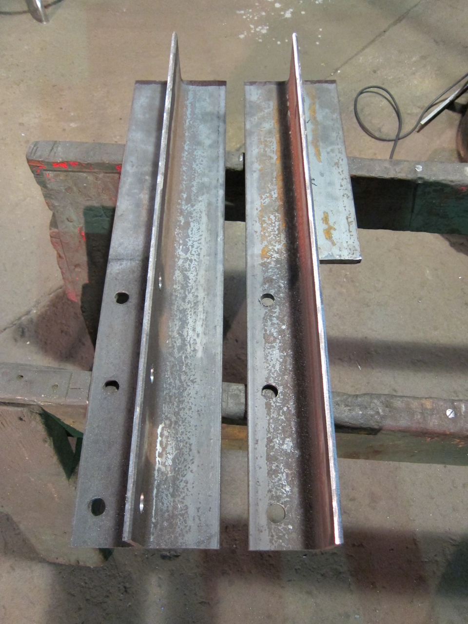
I cut two 31" stub posts from the new 20' beam, leaving enough material to replace one complete post should I chose to do so. All beam cutting, of old and new, was done by cutting the flanges with the steel circular saw and a drywall square, then finishing the web with a .045" cut-off wheel in an angle grinder.
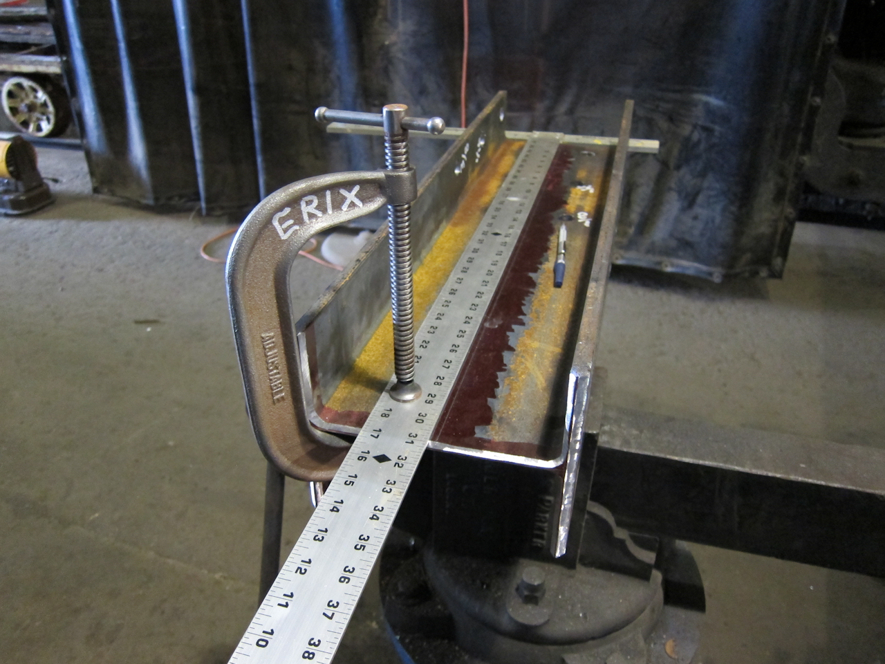
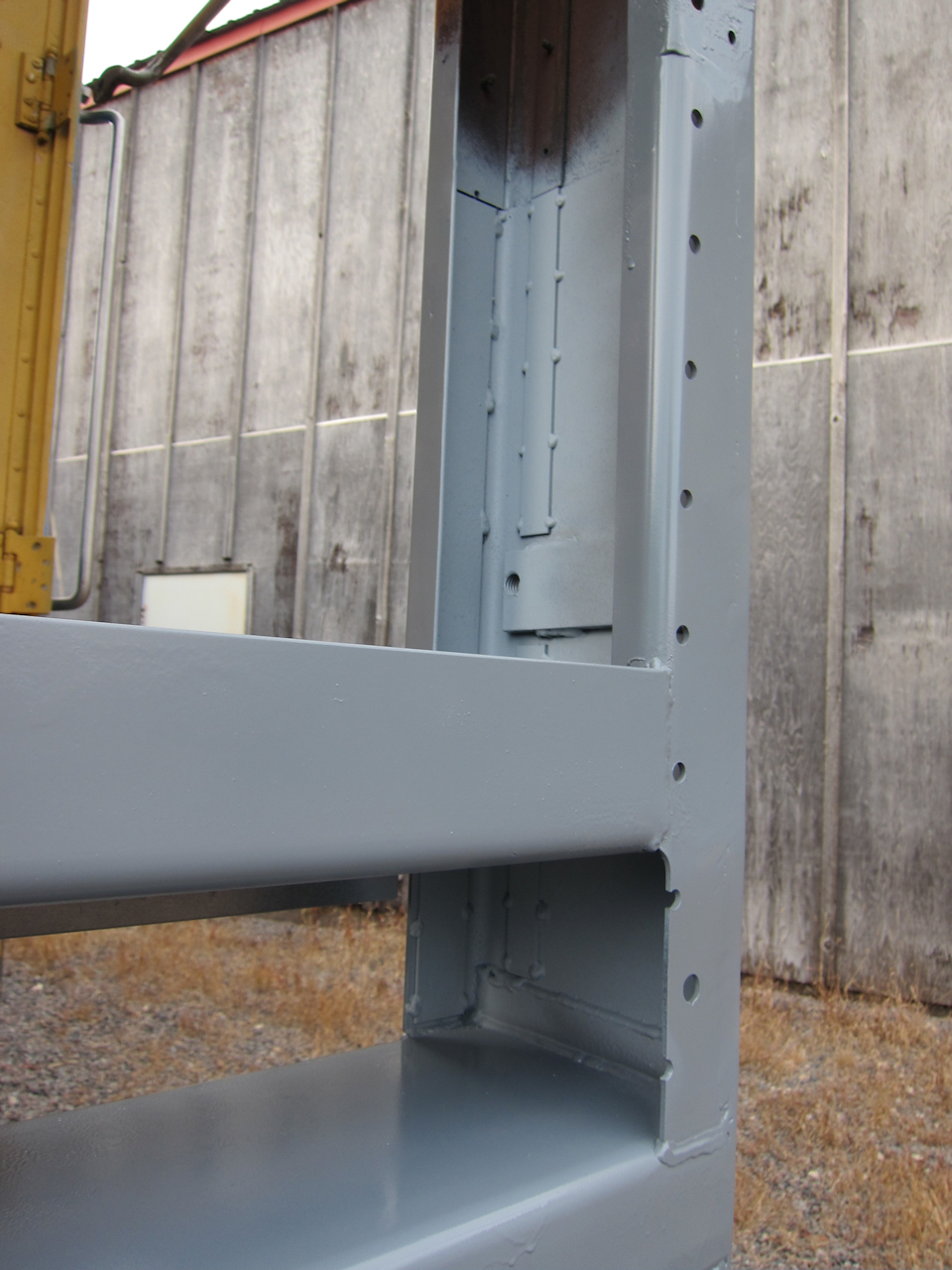
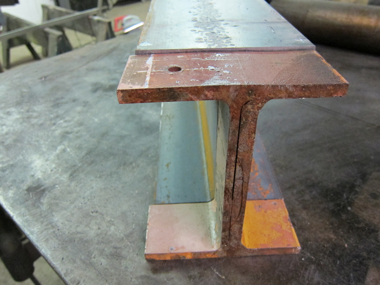 | Here is how the old and new collision post material compare. The old was exactly 8" over the flanges, but the flanges aren't straight. The new is 3/16" taller, but 1/8" narrower - on one side only. The web doubler on the old is actually called the "shear post" in the ACF bill of materials. |
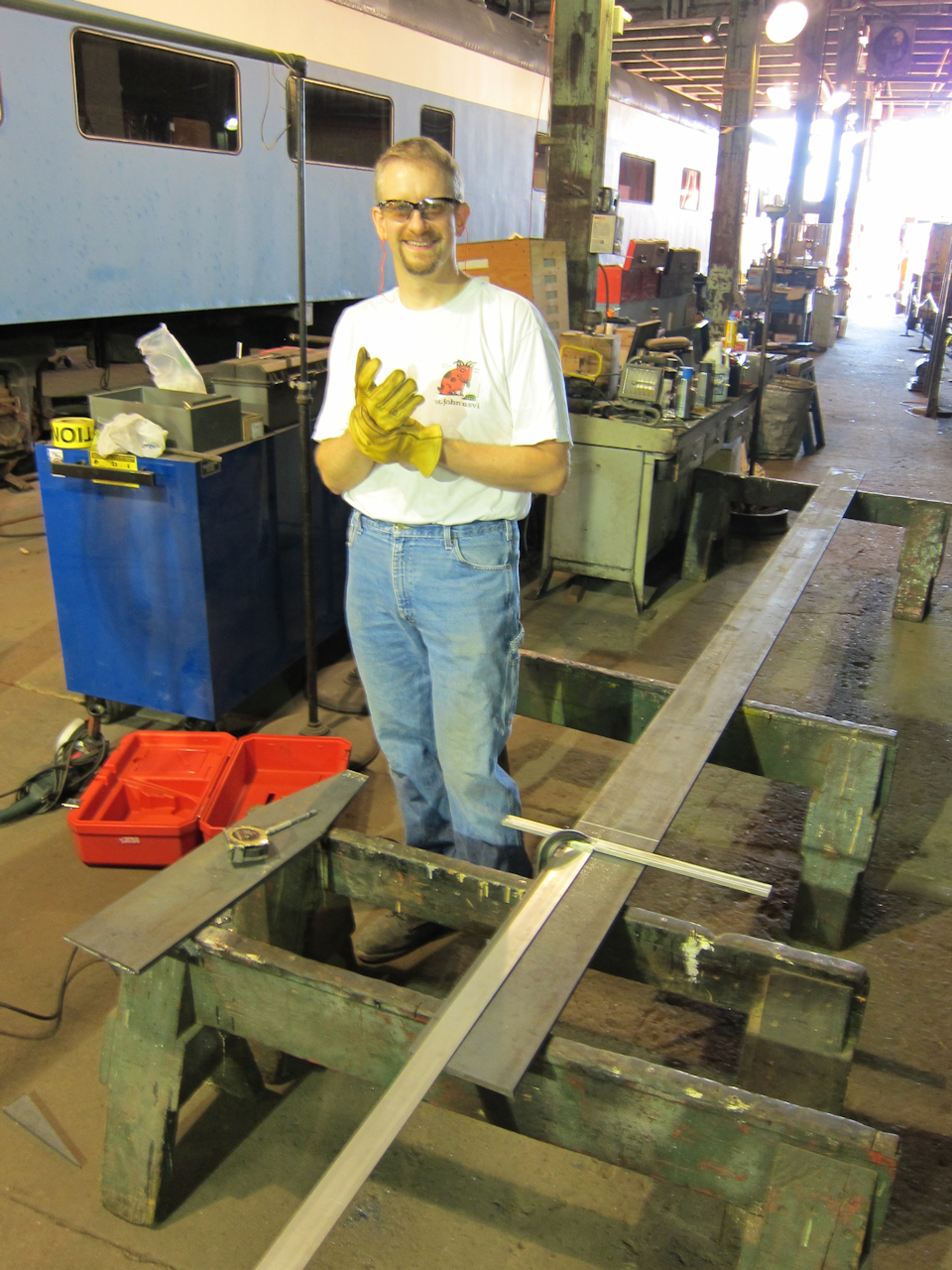
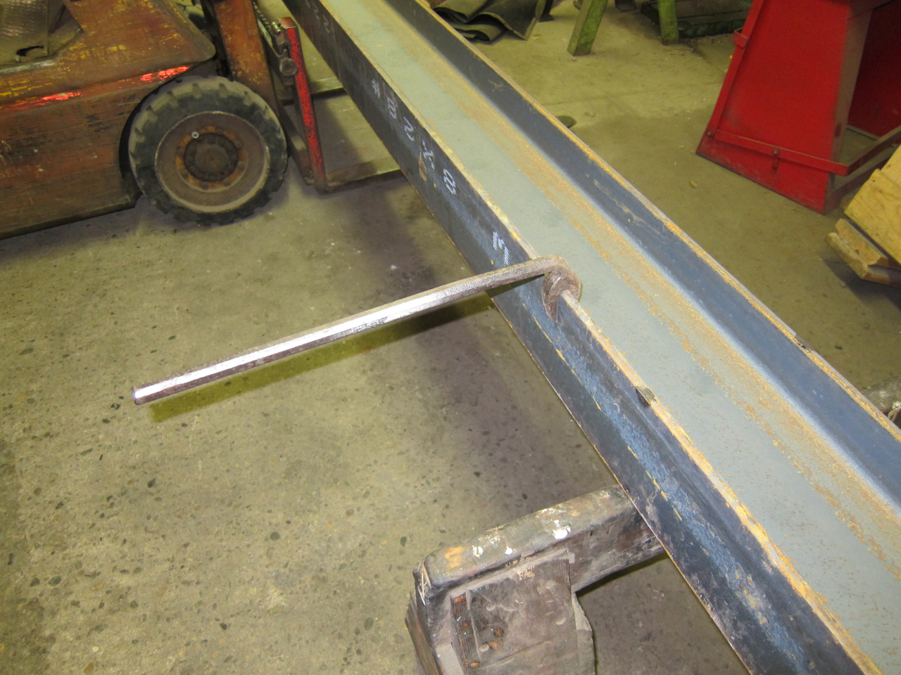 | My setup for cutting included two saw horses, a forklift, and this nifty little tool for rolling the beam. I have no idea what it's called or where to obtain one - my parents found it in a garage sale - but it has been dead useful for straighting bent edges and manipulating things. |
 | Making the cutout for the end casting with the plasma cutter. To account for the odd flame angle that occurs with a worn tip, and to minimize the heat-affected zone, I left a 1/8" margin and finished with the angle grinder. Note the old and new are side-by-side for comparison. |
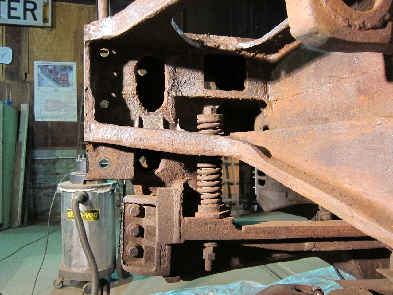
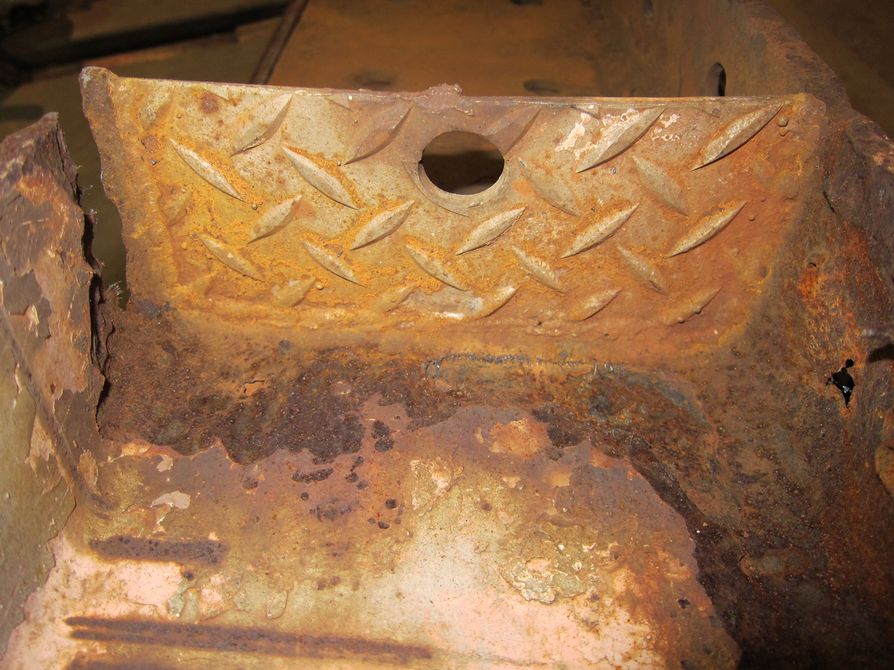
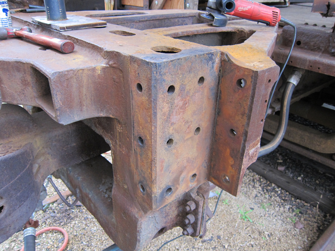 | This is what the end casting looks like without a post attached. Note the house jack centered between the posts to hold the roof up - and I only had one post out at a time. Also note the faint impression of shims on the right-most face. The casting allowed for thicker beam material, and ACF filled the gap with shims. |
 | I made a conservative cut, so I had to do some extra field grinding to get the new material to fit. |
I bought a slide on e-Bay which offers further proof that 1146 was never painted Big Sky Blue. There are several photos which show a Big Sky Blue coach/diner in a train, but the car number is not legible in any. That meant at least one was repainted, but which? With this new slide I have positive proof that 1145 wore blue. Coupled with this slide of 1146 in EB colors (processed after the BN merger) I am 95% confident 1146 was never blue.
Can anyone identify the location in the slide? Since it's coupled to a PC car I suspect it was taken in the Amtrak era.
An interesting post appeared in PassengerCarList@yahoogroups.com:
> Don't have a 1947 drawing, but 10/27/50 drawing D-5012 (Exterior painting
of the GN-CB&Q-SP&S owned cars assigned to the Oriental Limited, Pullman
built lightweight (Using Empire Builder colors; used in general service))
says vestibule walls & end doors dark tan, vestibule ceiling medium tan. In
the materials call-out, medium tan is #70-373 and dark tan is #70-375. The
steps, step wells and trap doors were green.
>
> FWIW, drawing D-5151 (1/29/51), for repainting heavyweights into Empire
Builder green & orange, also specifies light & dark tan vestibule interiors
and green steps.
>
> Tom Madden
Of all the GN cars I've seen, I never noticed a two-tone vestibule paint job.
When I inquired, Tom wrote:
Actually, what I have are scans, not paper drawings. They are from the
Newberry Library's Pullman collection and, unfortunately, the Newberry's
conditions of use prevent me from providing you with copies. I recommend you
purchase your own, but be aware that you'll need the Newberry's additional
permission to put them on your web site. Both drawings are under call number
05/02/03, Drawings, Linen. Drawing D-5012 should be in Roll 20, and drawing
D-5151 in Roll 21.
Go to http://www.newberry.org/collections/photodup.html and scroll down to the section labeled Pullman Drawings. TIFFs are $30 each,
and let them know the drawings you want have already been scanned.
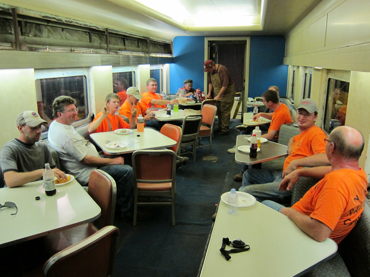 | I've discoverd I really enjoy hosting. (But you don't wan't me to cook!) After a hard day of Gandy Dancing, a four-state track crew enjoys burgers and brats in the dining room. We had MTM'ers from Minnesota, Wisconsin and California as well as IRM'ers from Illinois. |
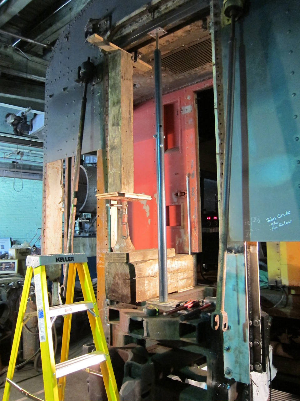
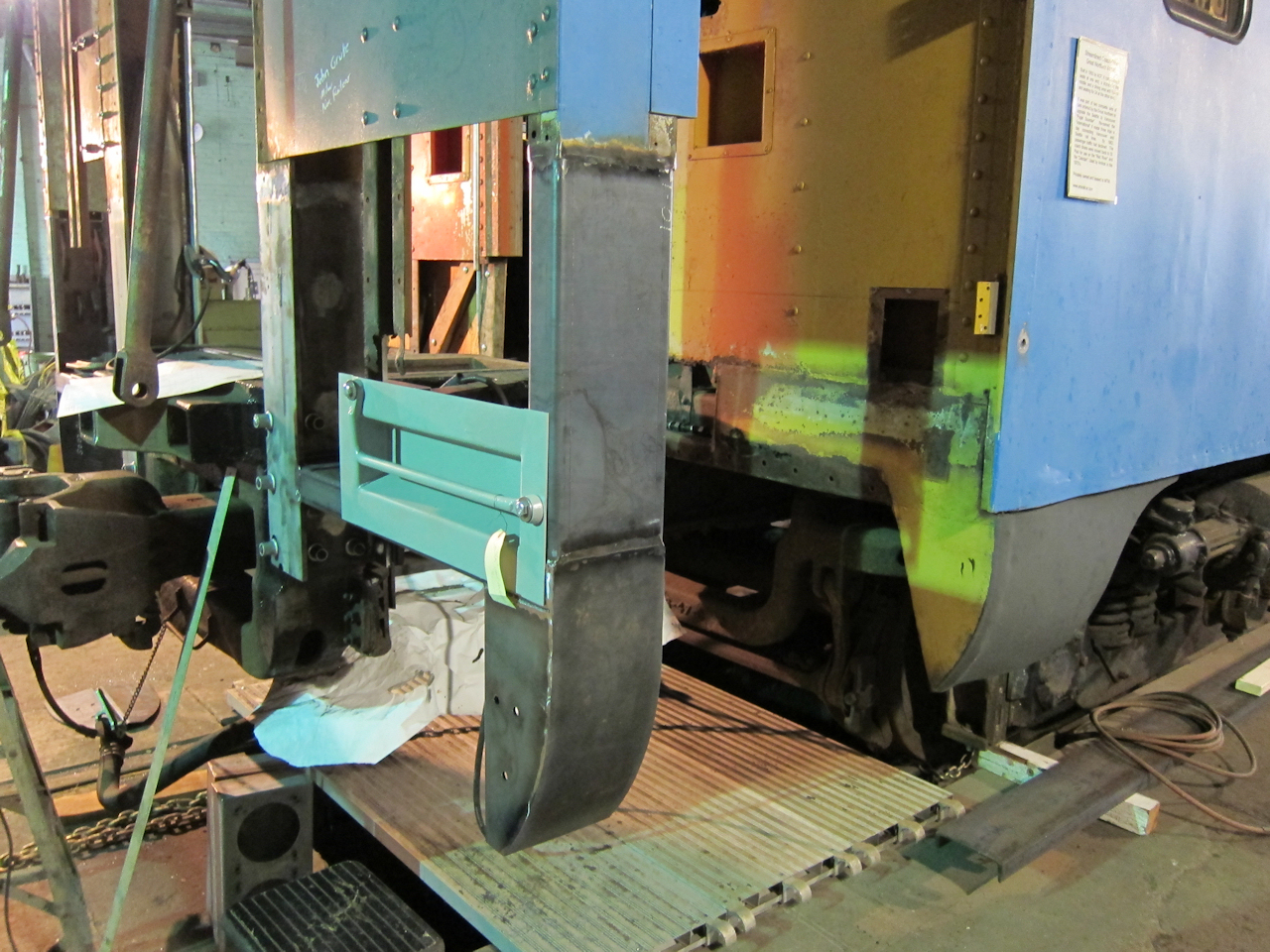
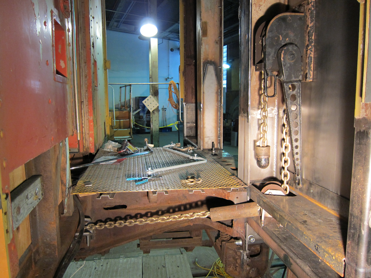
I took a week off work to get serious about collision post replacement:
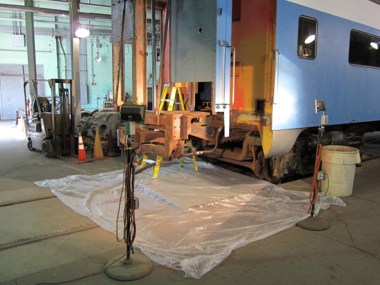 | Getting set up: Work lights, pit covers (aluminum scaffold planking) and plastic sheeting to catch the mess. |
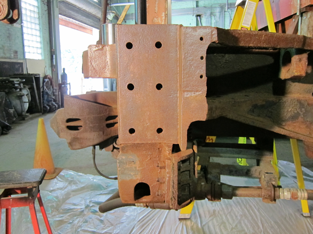 | The casting has been needle-scaled for rust-proofing where it will be covered up. |
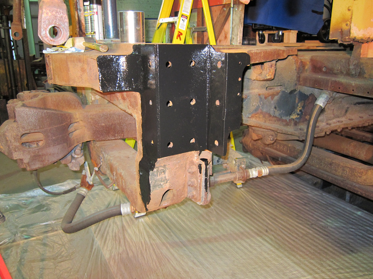 | POR-15 applied. |
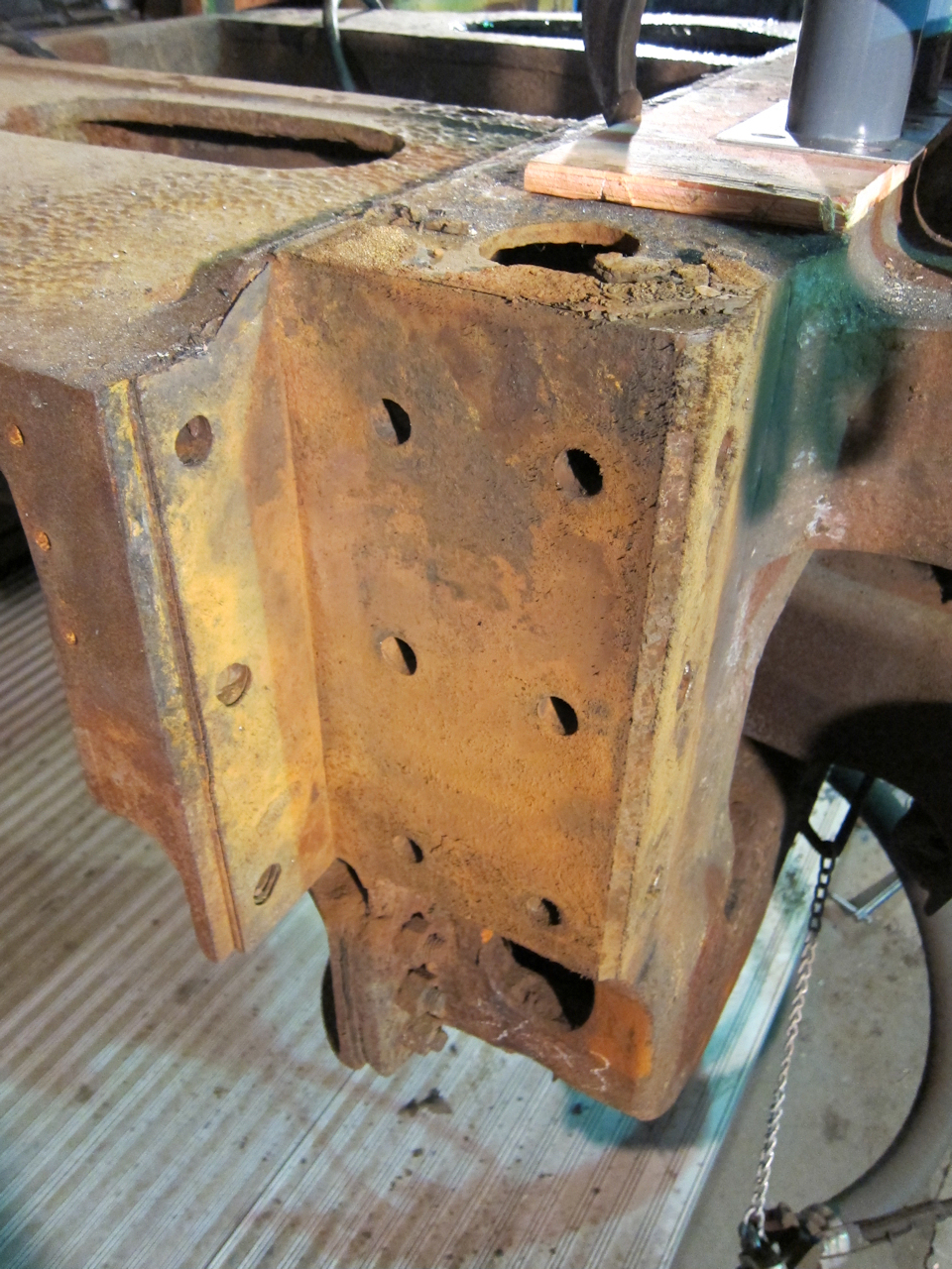
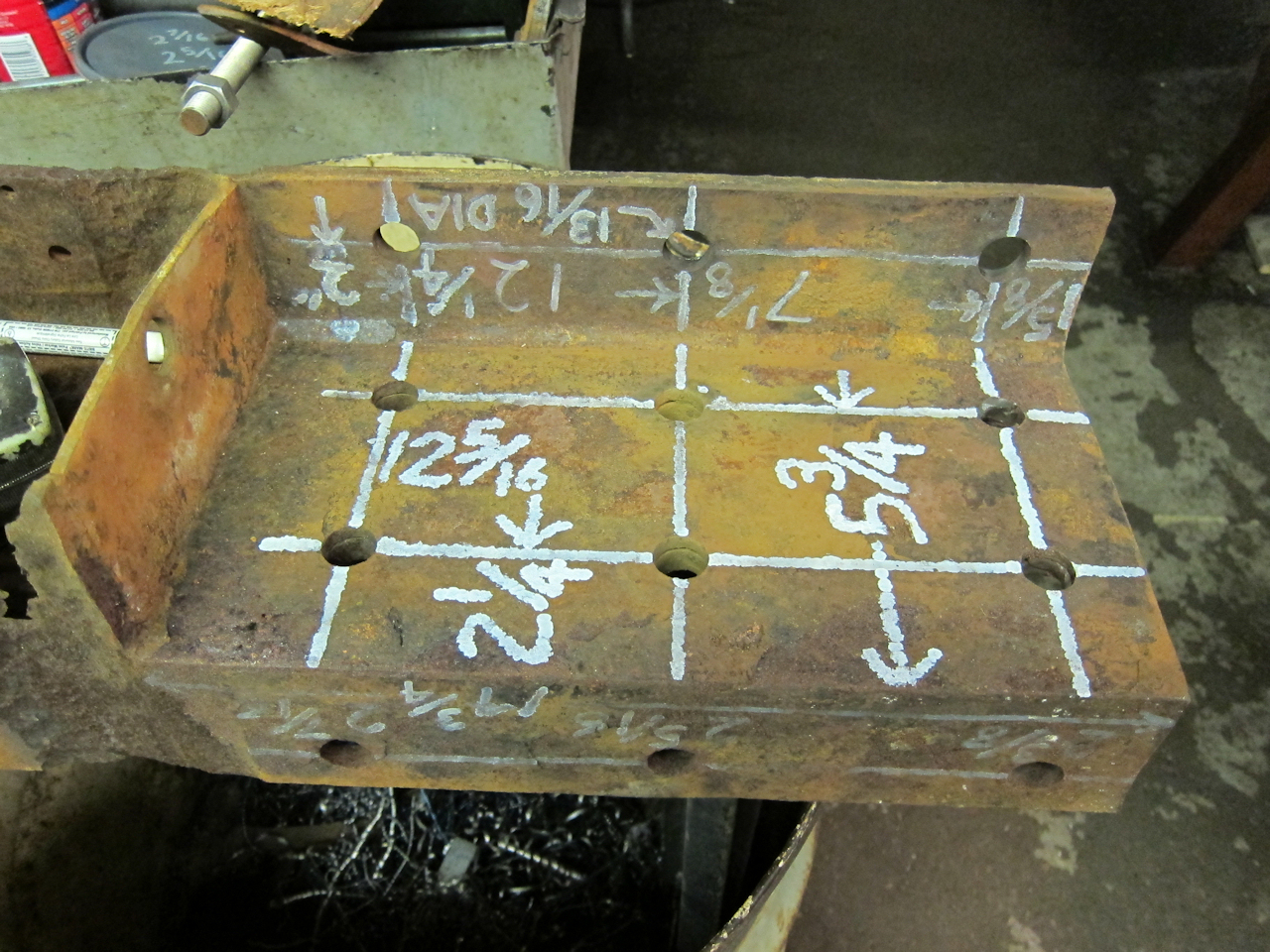 | I carefully measured the old beam to get the holes in the right places. 13/16" holes are required for 3/4" hot rivets. |
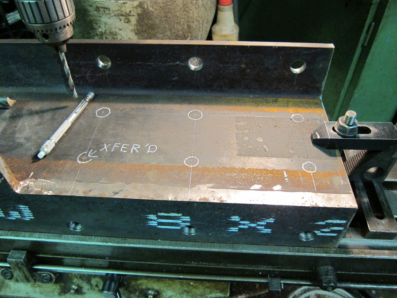 | Holes were drilled on the Bridgeport vertical mill. Each hole was pilot drilled and then finished drilled without moving the table. That's a lot of bit changing but we don't have a digital read-out. |
 | Looking though the end casting, the windows for accessing the back side of the hot rivets are visible. My hand barely fits through the lower hole. |
 | Correspondent and contributor Warren Newhauser from IRM was in town on business, and stopped by to help one evening. His own project is the Milwaukee Dynamometer X-5000 at IRM. |
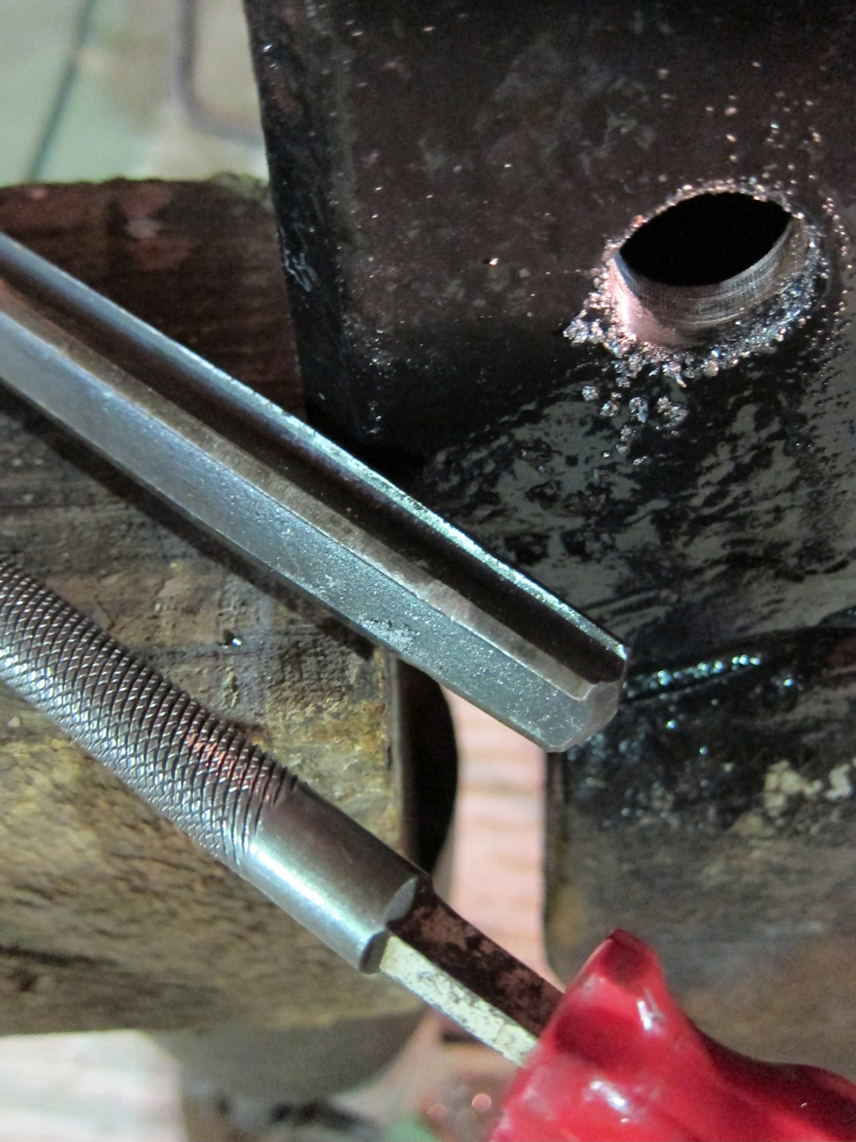
 | My carefully-drilled holes did not line up very well! It seems several rivets were in at an angle - especially the top-back which had to be reamed at a steep angle because of the flange on the casting. So I raided the machine shop looking for a quick way to adjust my holes. I found these tapered reamers and an air motor (stamped "truck shop" - hmmmm...) which have been around forever but which I've never seen anyone use. They were amazing! It took all of ten seconds per hole. |
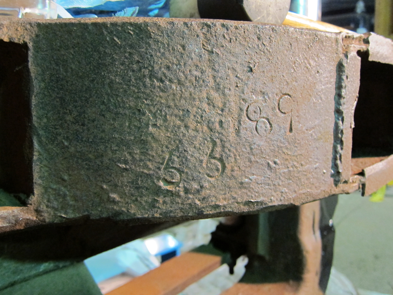 | Warren found this stamped on the end casting: "33 89". No idea what it might mean. The maker's logo and pattern number are cast in, so this was added later. |
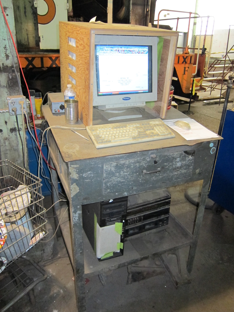 | MTM's shop is equipped for streaming music off the internet. It's also a great way to look at the engineering drawings from Starfire, which I posted on this web site. The main drawing for this week's assembly is 09053-A001 rev A. |
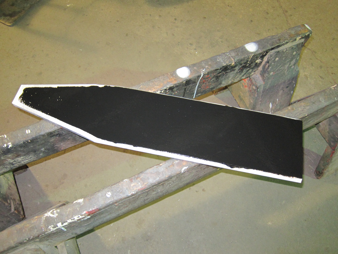
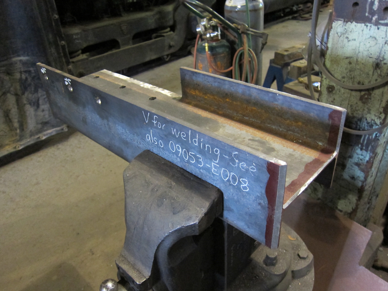 | The replacement post section vee'd for welding, according to Starfire's drawing 09053-E008. |
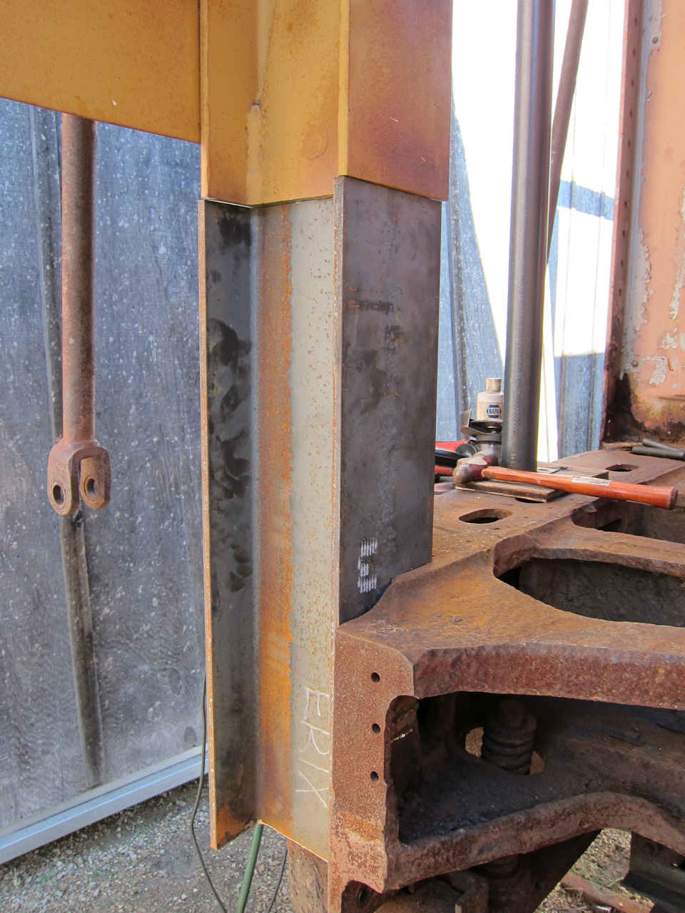
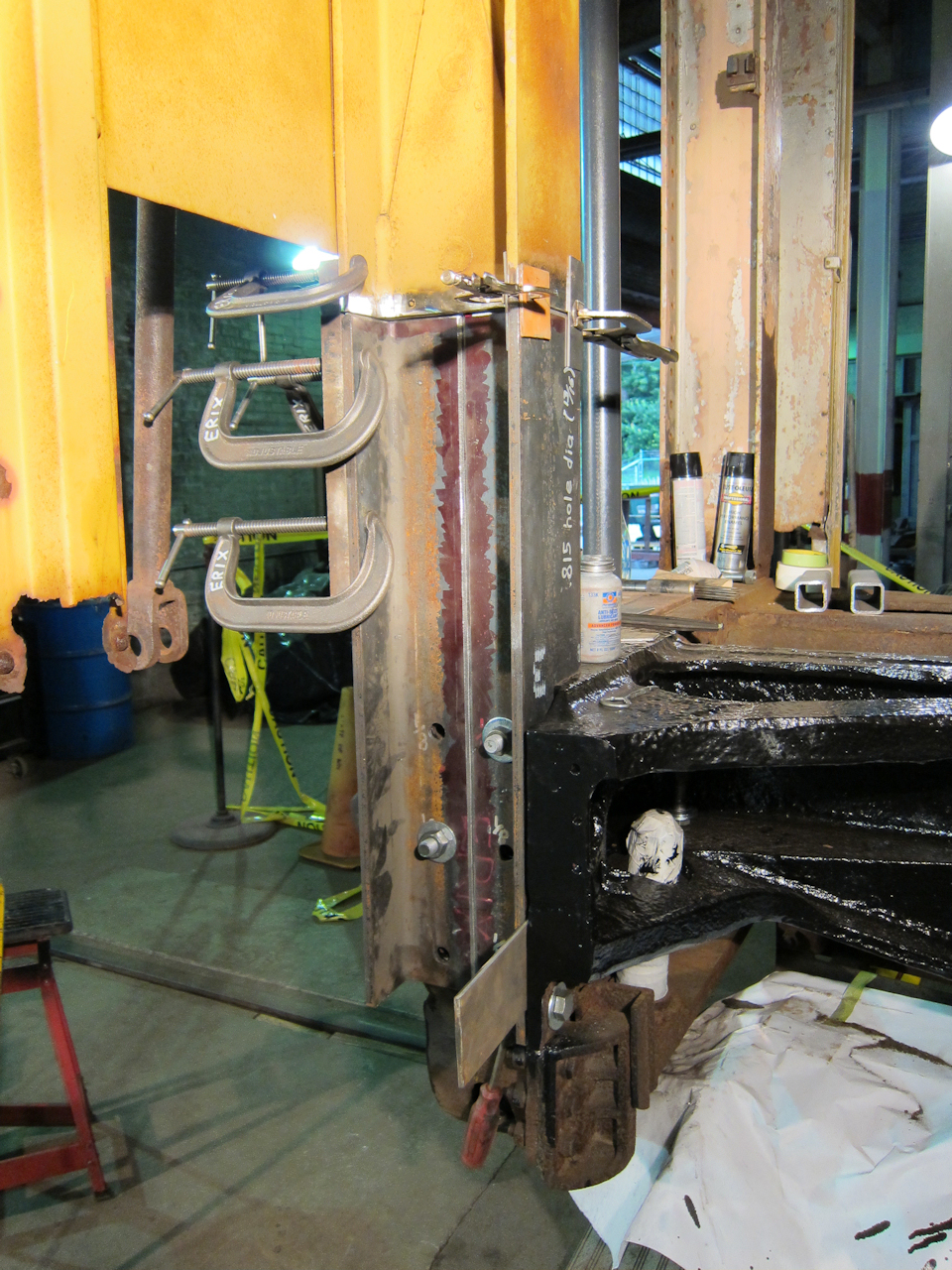
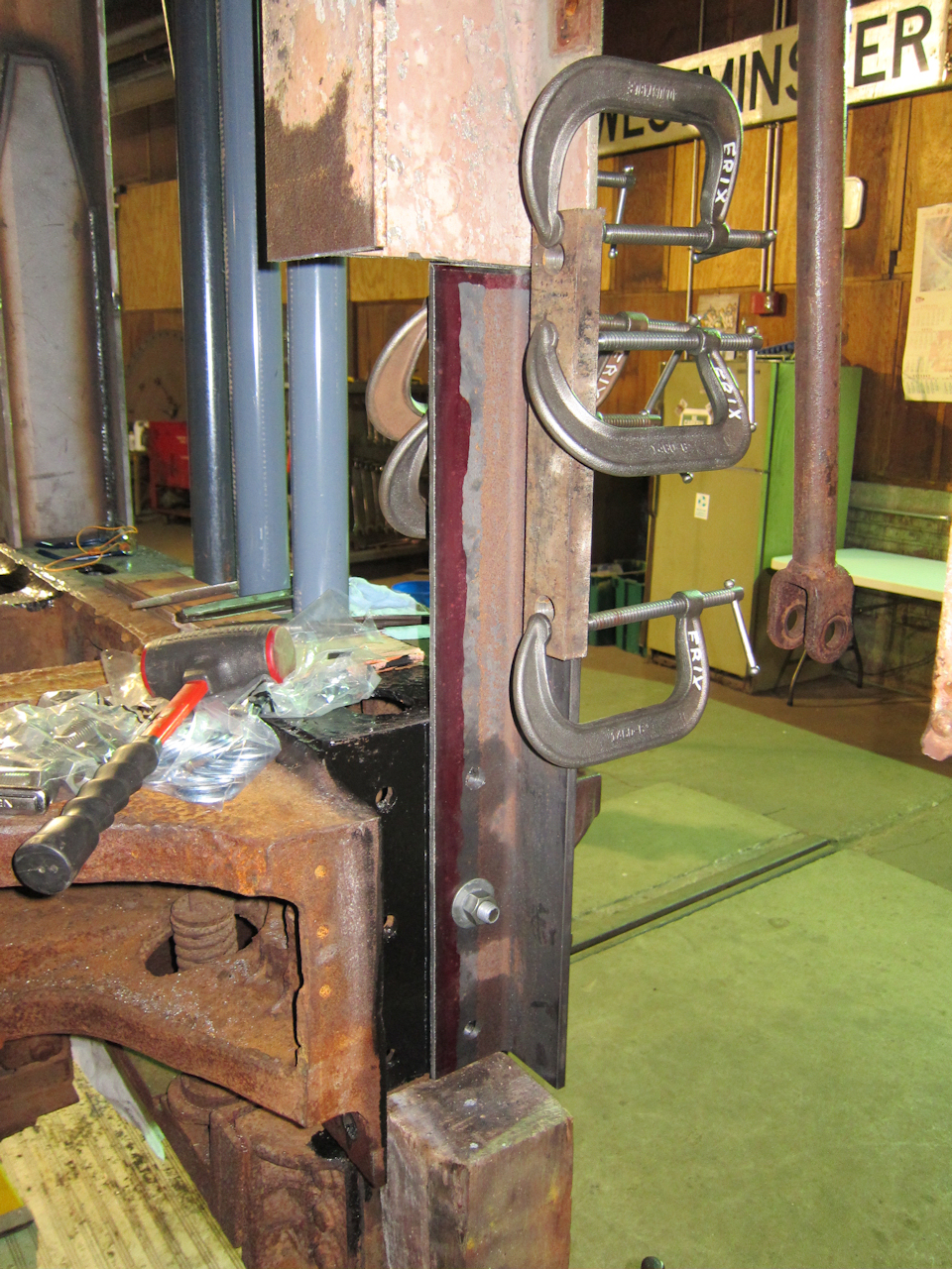
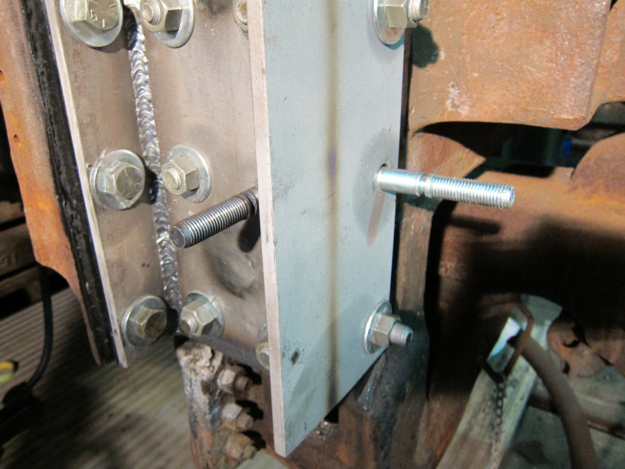
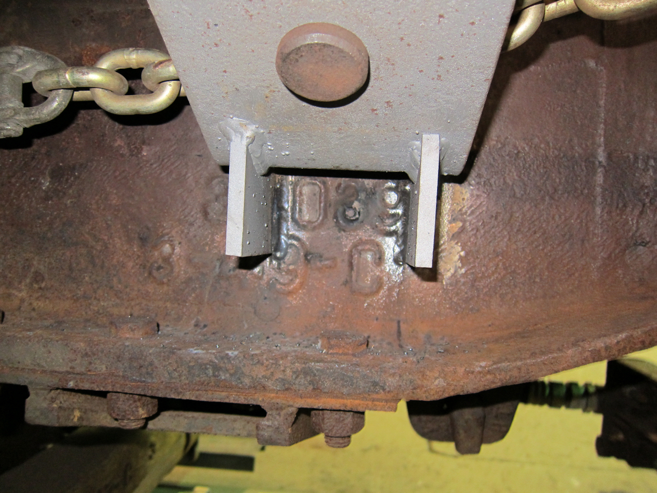
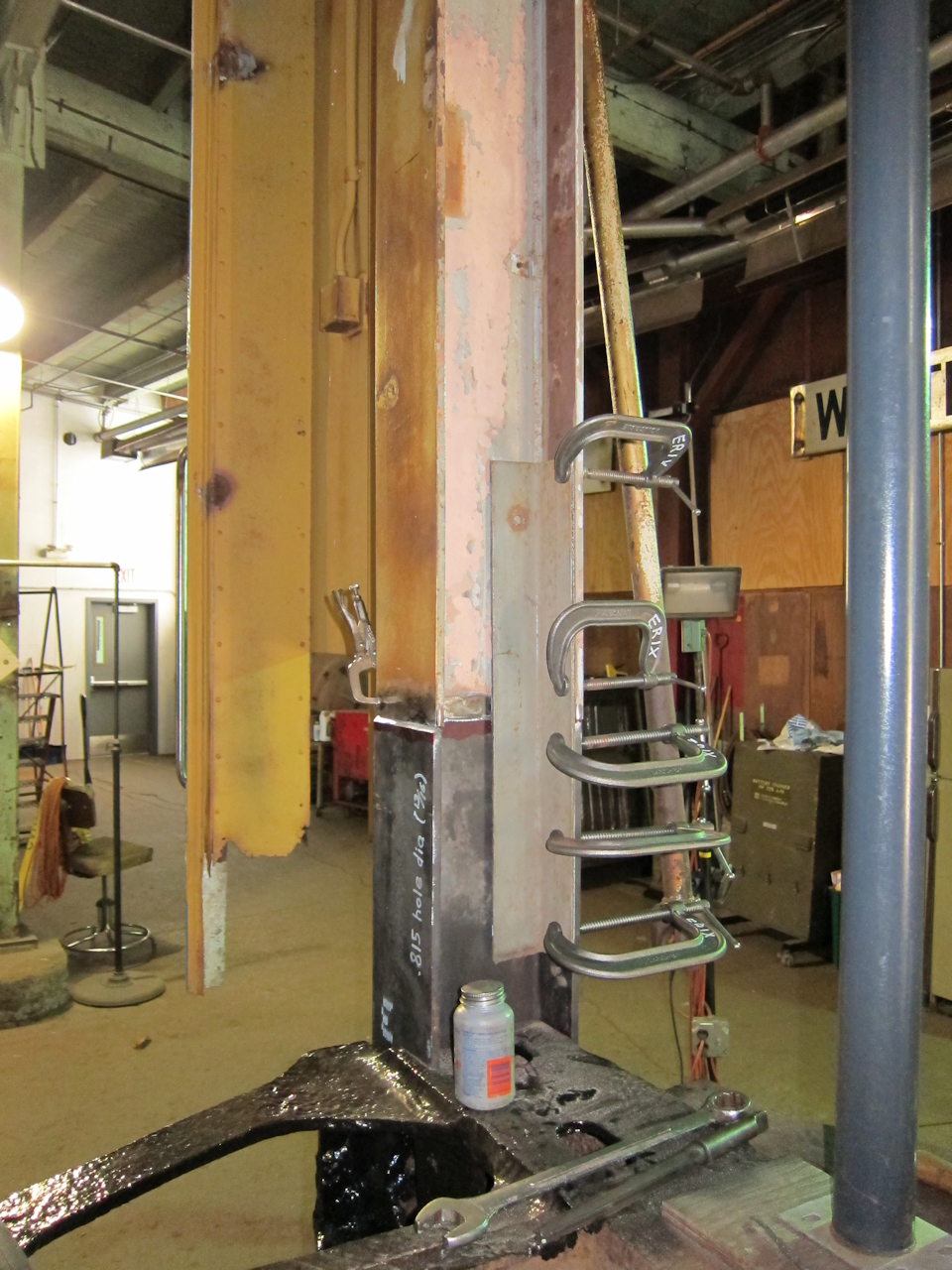 | After the replacement was bolted to the end casting, bar stock and clamps were used to fine-tune alignment. At this point I still hadn't decided whether I would replace just this portion or replace the entire post. I was thinking the partial post would just be a pattern for the full-length post. |
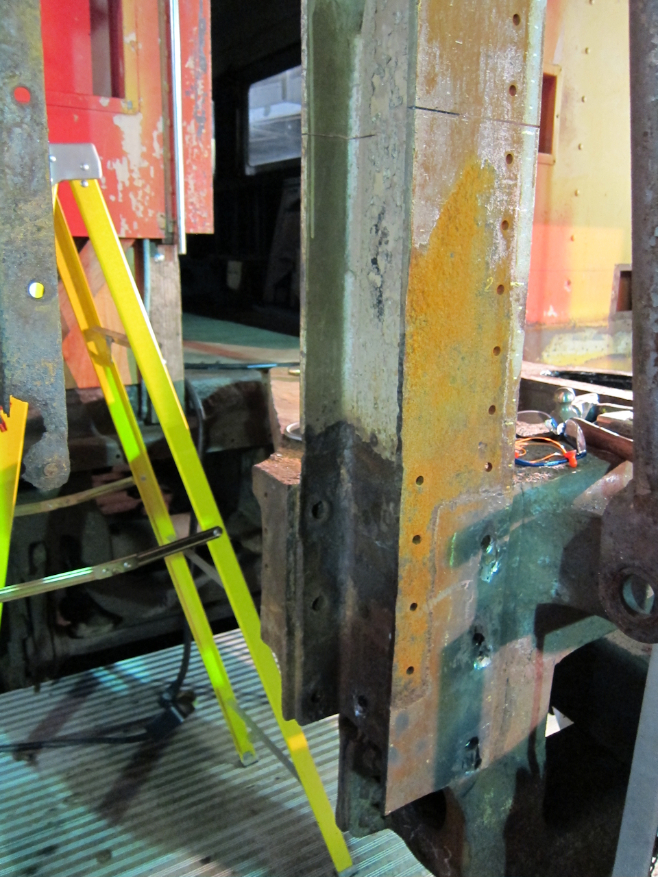
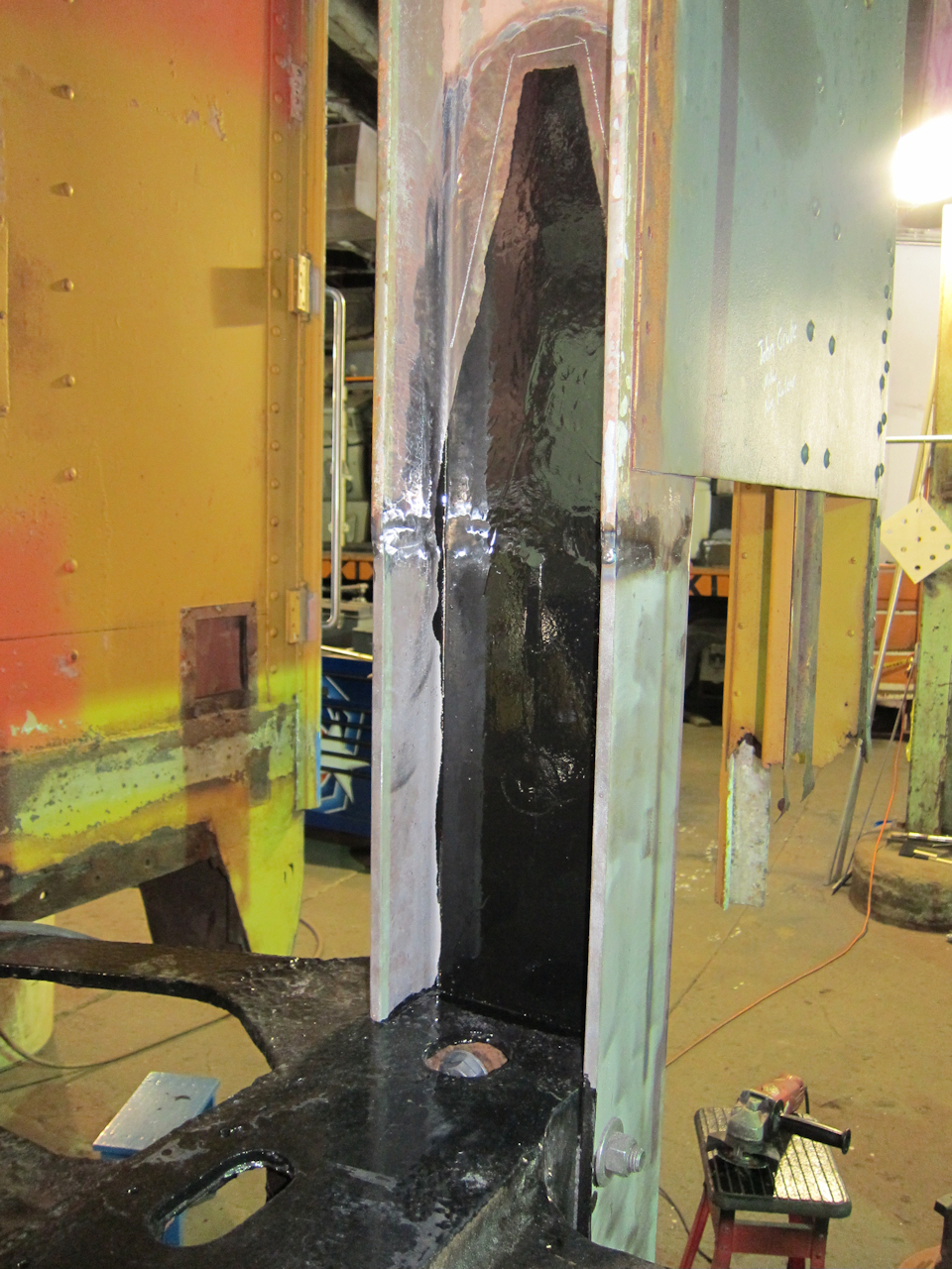
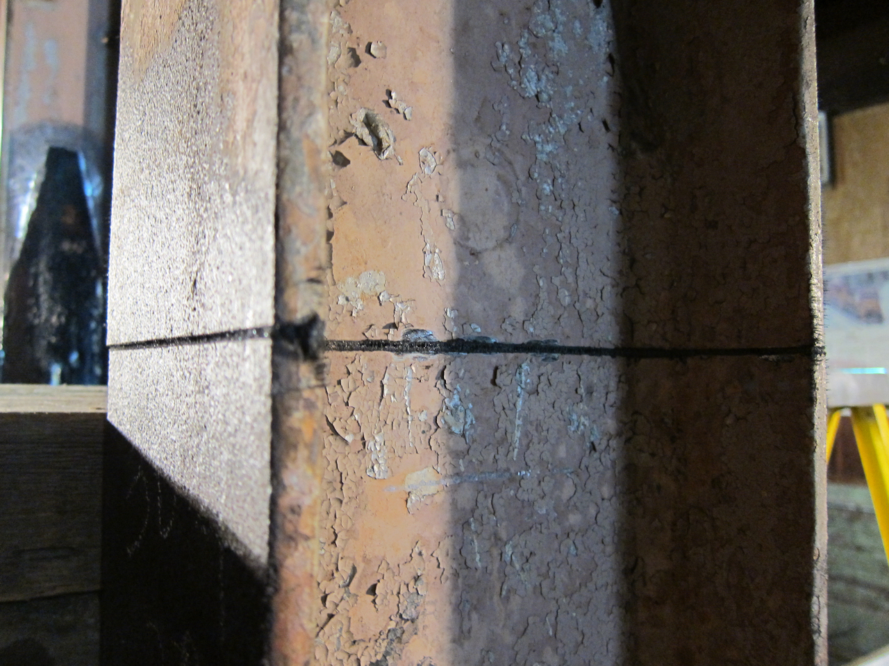
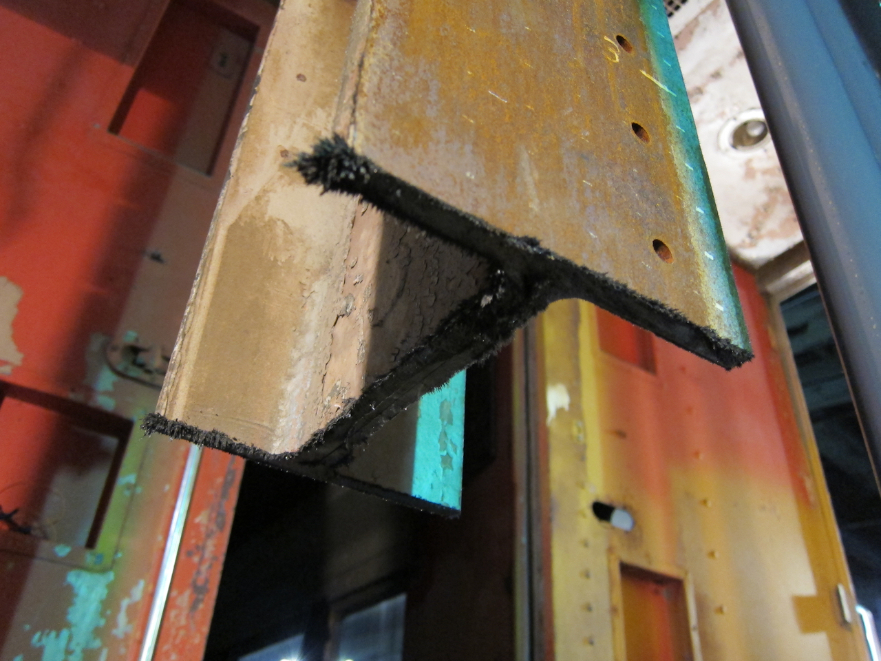
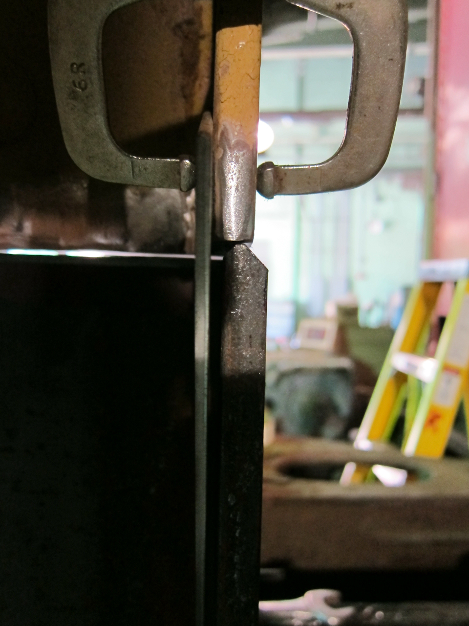 | Here is my problem up close: If I weld it in like this, it will look horrible - and it will be right at eye-level every time I get on the car. |
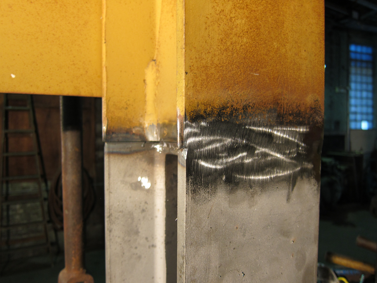
 | Last January my local Amtrak car inspector had suggested cutting the beam right down the middle of the web to correct its flange-to-flange thickness. That works structurally because the strength is in the flanges (tension on compression faces) and the web is just there to keep them spaced properly relative to each other. Starfire OK'd the idea in a May 26 e-mail, so what the heck, I think I'll try it. |
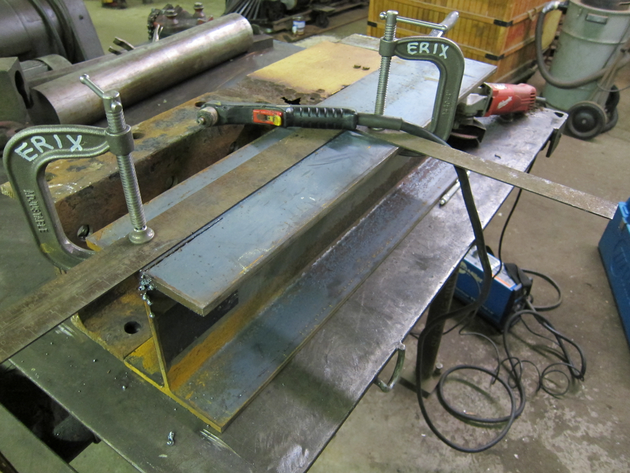
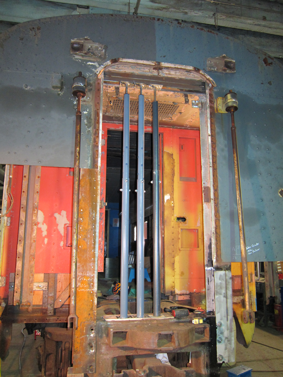
 | It actually worked really well. Because I could clamp each half in separately, I was able to adjust for twist in the original beam. It was also the best jig I could come up with for clamping to prevent distortion. This is about when I decided against replacing the entire beam. I had planned it all out and it would have been several weeks of work, and the parts would have had to be craned in and out. |
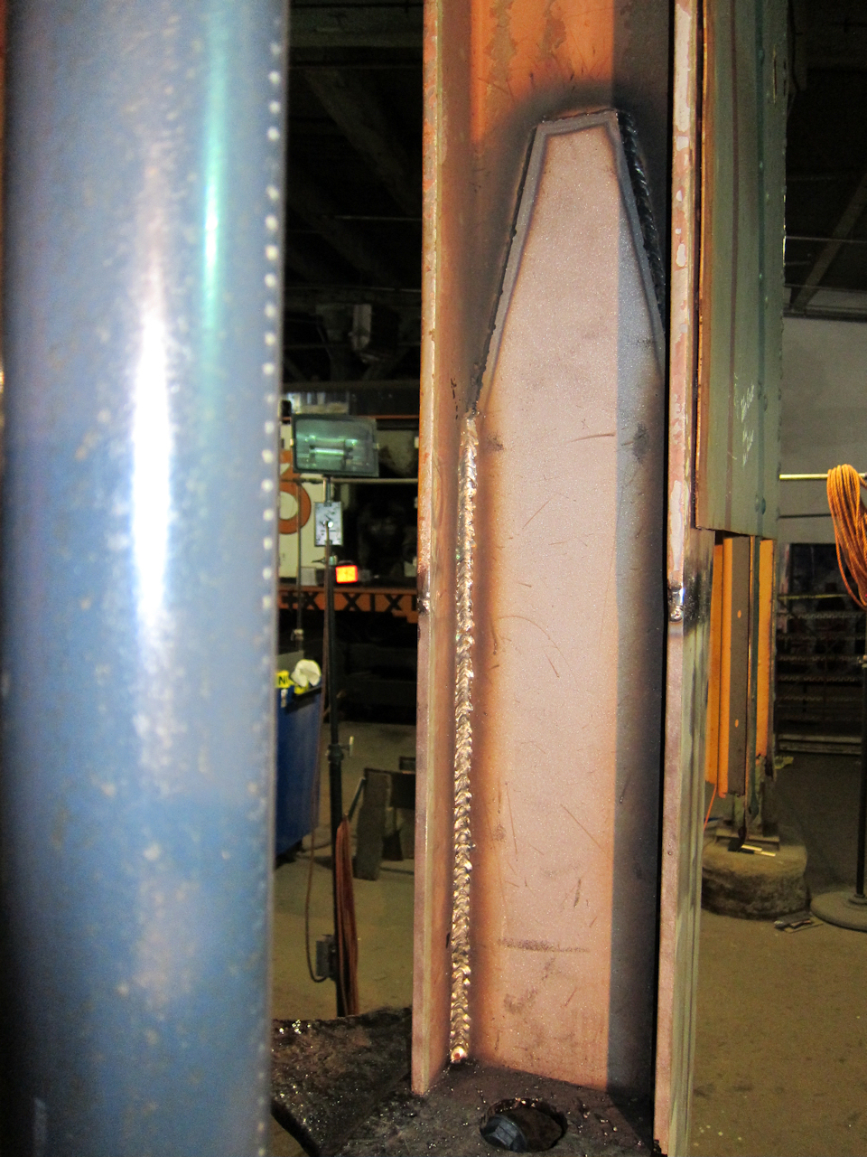
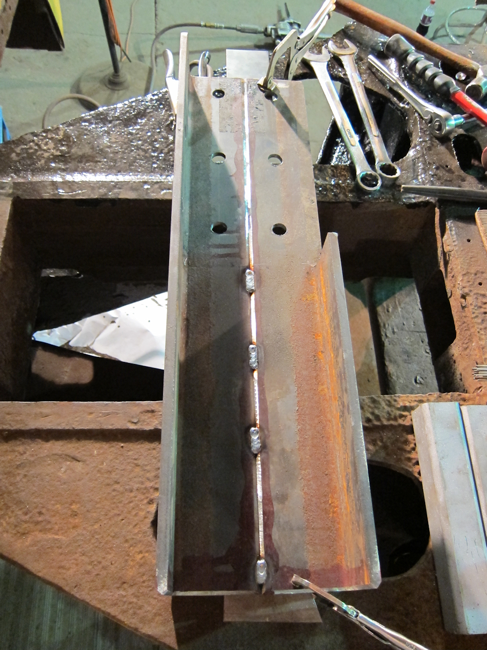 | After tacking, I took it down for welding in flat position, which is the easiest position to weld in. |
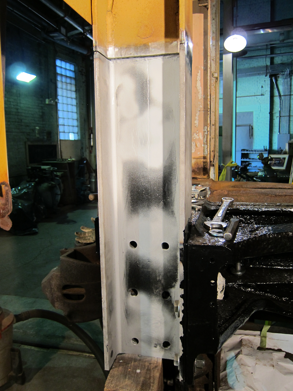
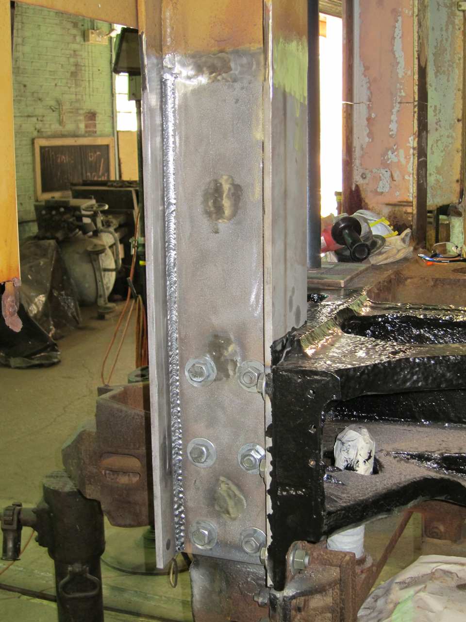
 | Here it is after grinding the welds smooth and sandblasting. Starfire OK'd the beam modification with the provision that there be no porosity in the welds. No porosity found. |
 | As before, I put POR-15 rust-proofing on the face that would be covered. POR-15 does not stick to clean steel, but I've had excellent luck with sandblasting it before painting. (The paint can has no label because I buy by the gallon for the cost savings, and then divide into quart cans to control loss.) |
 | Matt Arnold was available to help for one day. I've never hired help before (aside from abatement) but I've seen his work and his cost was reasonable. For more info, he and his Dad Mark Arnold are Lake Superior Companies. |
 | Friend Paul Landgrebe was also available to help. He took care of cutting the shear posts and double plates. |
 | All this work getting done, and I'm goofing off taking pictures! (The yellow caution tape is up because this was Wednesday when the museum is open, and we're basically working in the main aisle of the shop. We had to cease and desist when the docents led tours through.) Matt caught me making a mistake: I was going to bolt tight to the end casting before joining old and new, which would have left a very, very slight kink at the joint. Instead we left the bolts loose, jacked it to maintain elevation, and clamped it straight. |
 | This 3/8" vee is not for welding. Instead it fits the shear post replacement into the round corner of the beam. (Note the photo comparing the new with the sample of the old above.) The weld will actually be on the flat side. See 09053-E010. I believe I found an error in the drawing. The top end should be chamfered on back to clear the collision post weld, which we ground with a ball-end burr, but it should also be chamfered on front for welding. |
 | While the right-side collision post progressed, we removed all but one rivet from the left post and saw-cut the flanges. That was all I was willing to do until the right side was secured. |
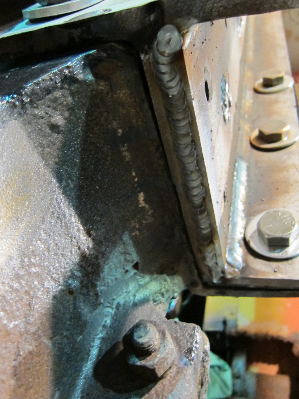
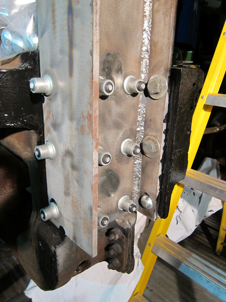
 | Initial welds are done on the right-side post. After being narrowed, the new beam is a pretty close match. |
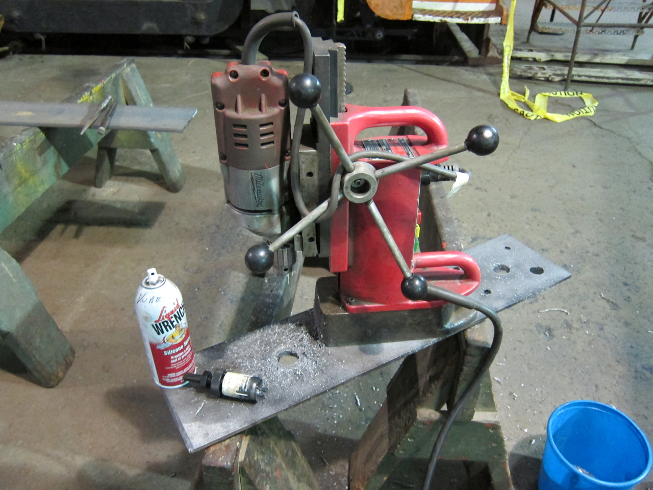 | A good magnetic-base drill is a treasure. The original shear post had plug welds, so monkey-see, monkey-do, I duplicated them. Applying pressure when cutting and stopping frequently to clear chips and lubricate/cool with light oil did a great job of preserving the cutting edge on my hole saw. The spray can got it all over though... |
 | Before doubling, I rust-proofed with POR-15. If it burns it causes porosity in welds, so for the last 3/4" I use a NAPA weld-through Zinc primer. |
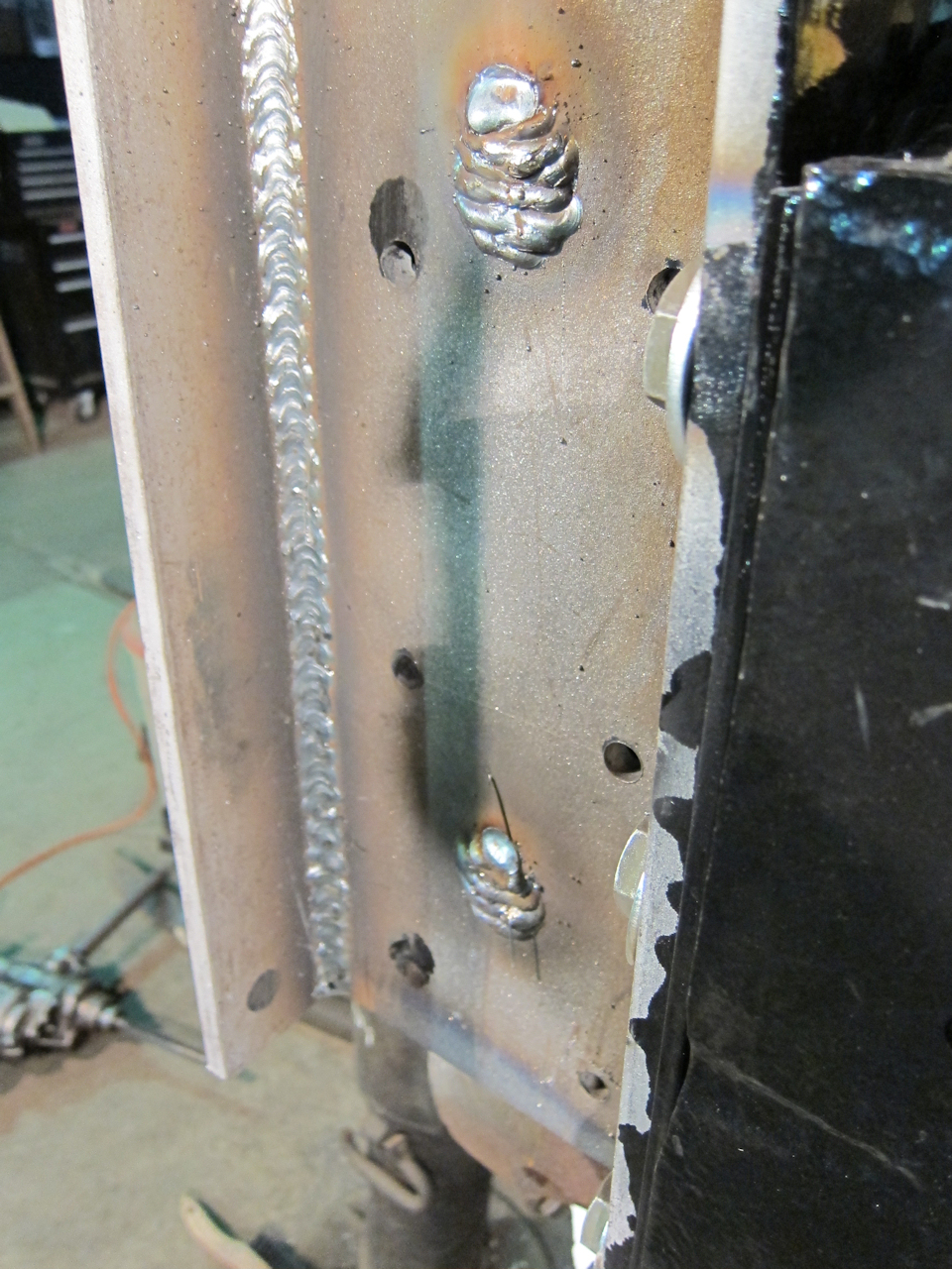 | The corners were welded with two passes, vertical-down. I used the Millermatic 252's recommended settings for 1/2". For the plugs I turned it down to the 3/8" settings to control bead droop. No porosity noted. |
 | Another view. On this side I had to start and stop the bead, because I only wanted to remove one bolt at a time. Note the holes in the shear post are drilled undersize. In a change of plans, I decided to ream to finished dimension in place for better alignment. It worked well. |
 | The engineering also called for a weld on the bottom of the collision post and shear post. (I really don't like overhead welding!) So I turned it down to the 1/4" settings, and let it freeze as soon as I had a decent puddle. This is the second pass. By the way, all welds were done with ESAB .035" ER70S solid-core wire - about as generic as it gets. |
 | POR-15 rust-proofing on the inside of the inside doubler, after sandblasting. This piece was cut per 09053-E007. |
 | Same on the inside of the collision post. |
 | The outside of the collision post is finished: Plugs ground and then smoothed with a flap wheel, holes reamed and temporary bolts installed, and flange edges smoothly joined. |
 | Not good. When I finished cutting the left post with the .045" cutoff wheel, the gap closed and pinched my blade. My lone house jack wouldn't raise the post to open the gap, so I grabbed some blocking and a screw jack to see how much trouble I was in. |
 | The cut is pretty tight. |
 | Blocking and a screw jack worked, but left no work room. Off I went to Menard's for a couple more house jacks. I opened it to where I could just fit the steel saw blade in (and broke off enough carbide teeth to retire the blade.) |
 | The left corner of the casting. Note the shims are still in place, held by rust, and the big pile on top that built up under the stainless deck. |
 | Curious - why is the left post so stongly magnetized? I could actually feel it grab when I was test-fitting the new post section. |
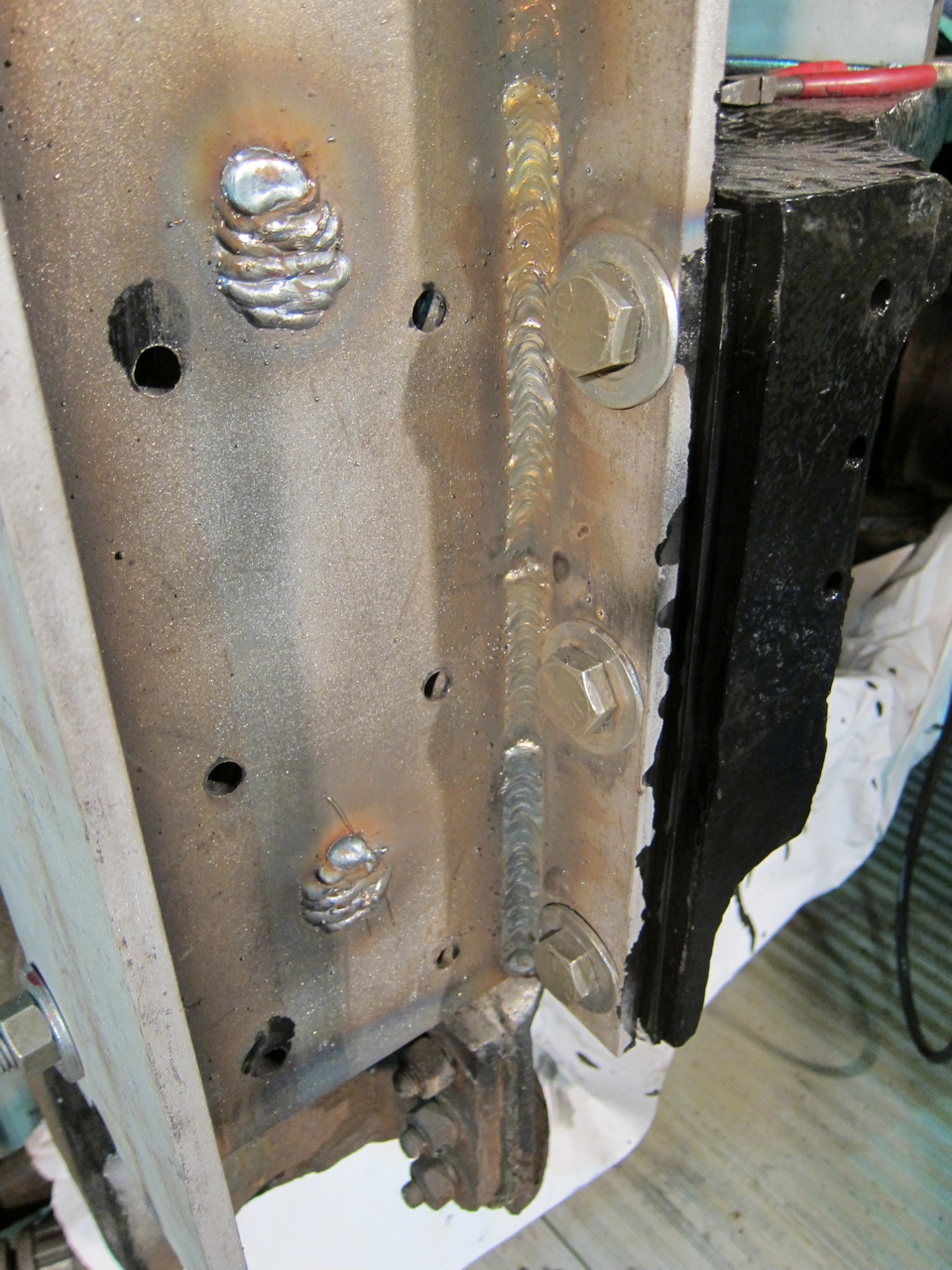
 | The right-post inside doubler, after two passes vertical-down. The nicks in the left angle are from my wire getting too close to the doubler's corner in the tight space. Starfire did a great job making the addition look original. There is no weld at the bottom, as specified. Instead I used POR-15 on the bottom edge. |
 | It just looked too cool to NOT take a photo. |
 | Old and new (left side) next to each other. Zoom in and one can really assess the pitting damage to the old post. Note the ACF shims lying on the floor nearby. |
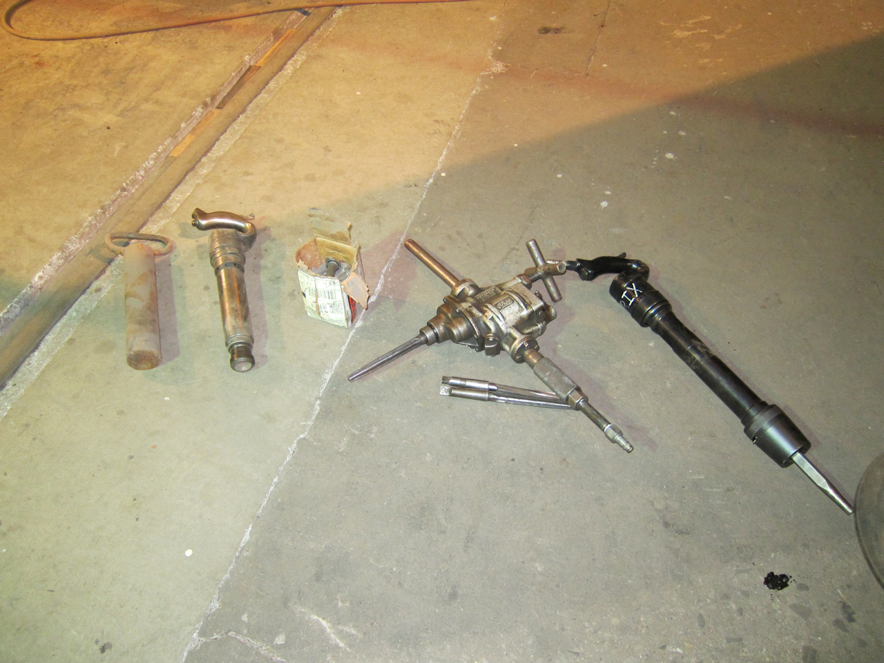 | For Saturday's museum visitors, I laid out the hot riveting tools. From left to right: A crude bucking bar (mass is important,) a rivet gun with 7/8" set, box of new 3/4" rivets (I have no idea where they came from,) air motor with tapered reamers, and my 11" rivet buster. |
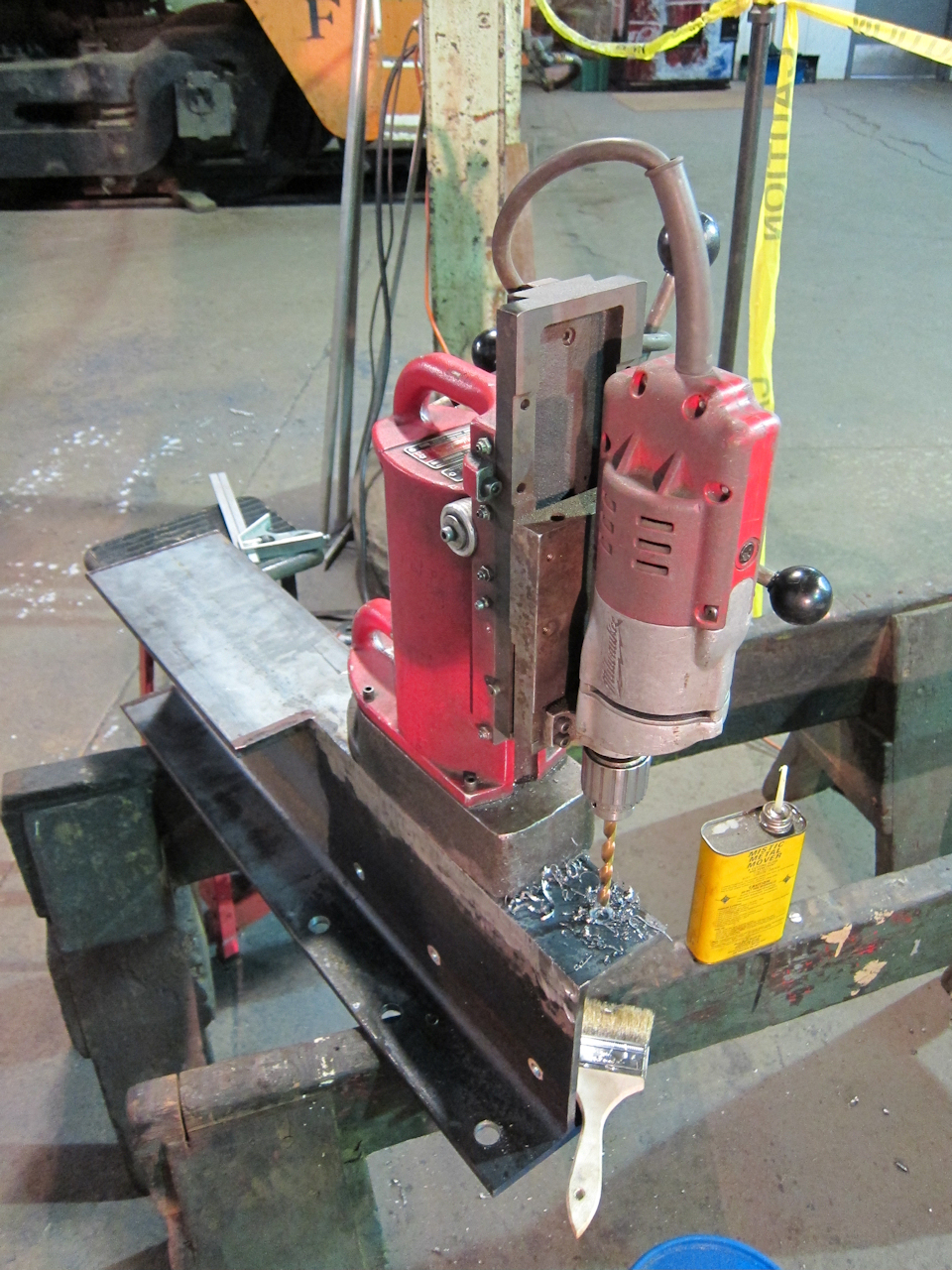 | New plan: Mark in place, drill the smallest hole possible, and ream to size. I found a can of Mistic Metal Mover that worked well to lubricate and cool the drill, without spraying it everywhere. Menards and Home Depot sell chip brushes in the paint section. They're terrible for painting - they leave bristles behind - but they work wonderfully for sweeping steel cuttings away. |
 | I damaged a reamer in one hole. There was a hard spot, which ground a dull spot in each cutting edge. This reamer is now only good for holes of a larger diameter than the dull spot. In a smaller hole it the dull, cupped spot forms a shoulder that stops the reamer in its tracks. I had been running dry, so I tried another reamer in the same hole, but well-lubricated. It also started getting damaged. I checked the depth and it appeared to be something in the casting, rather than the beam. Therefore I finished the hole with a "rat tail" round bastard file. |
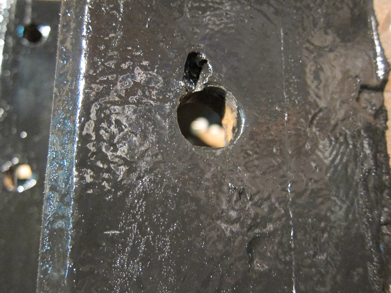 |
As near as I can see, this is the culprit: The edge of the hole in the casting had been nicked with a cutting torch at some point. When is a mystery, since the last time this was exposed was at the ACF factory in St Charles. I deliberatly did not use a torch to remove rivets, to avoid just this problem.
When I recycled the old post, I noticed the cutting torch had completely penetrated when cutting off the rivet head. Sloppy - guess this was self-inflicted. Ouch. |
That was six day's work. On the seventh day I rested!
 | BL post partly drilled, then split down the middle. Note the web on the right is not drilled - since I drilled undersized and reamed in place, and those three holes would move when I narrowed the beam, I left them undone. |
 | First half supported and clamped in. The secret to success is getting everything aligned perfectly before tack welding. I probably spent three hours making small adjustments before I was happy. |
 | Before being recycled, the old post shows how the stainless deck plate filler was welded in. It also illustrates how deep the rust pitting is. At lower right the web is completely gone, revealing the back of the shear post. |
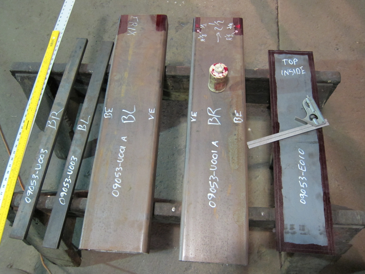 | The BL shear post replacement has been marked for bevelling the edges, and thinking ahead, the parts of the end sill tube assemblies are laid out. The bar stock will be welded inside the tube as a tapping plate for the bolts which secure the vestibule steps. About my scribbles: "BE" is body end (step side) and "VE" is vestibule end (end sheet side.) "BL" is the left corner when looking at the B (handbrake) end of the car. |
 | I know what an SW1 is for - serving as my workbench! |
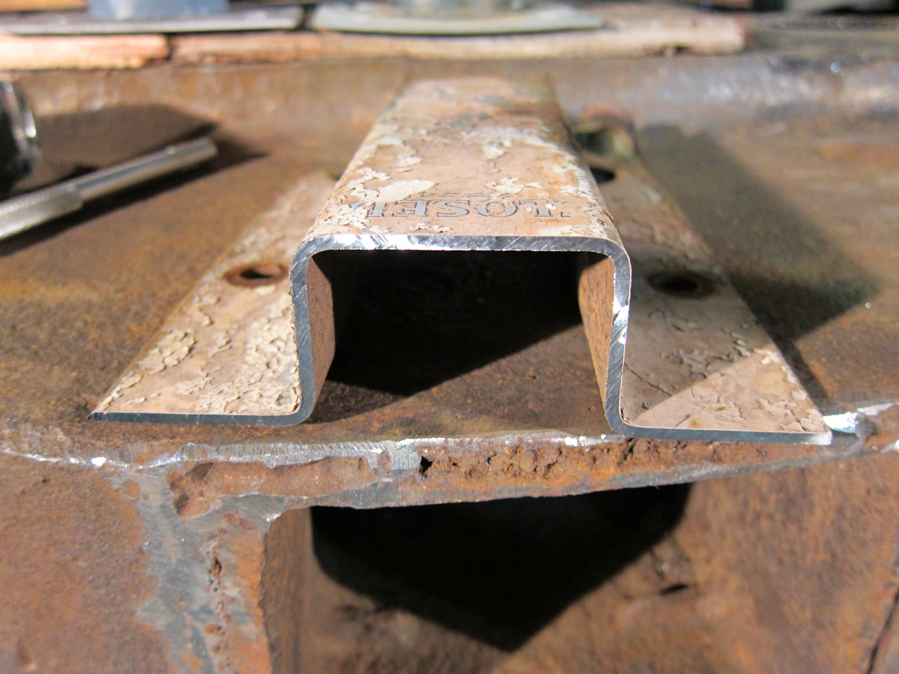 | Getting ready for my October work session, I cut a sample of the vestibule end sheet stiffener. ("Closed" is part of the steam heat trainline valve operating instructions.) On the ACF Vestibule End Frame drawing and in their Bill of Materials, this is part VE32355. This sample, and print-screens of the drawings, went to Linders to have new ones made. They are also making body end sills and vestibule platform framing. |
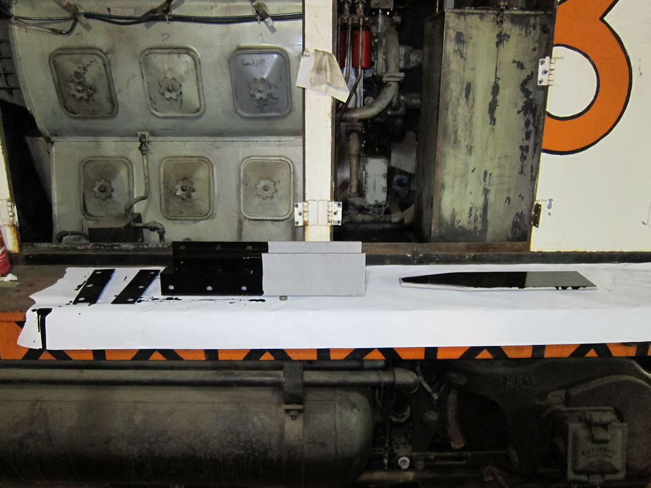
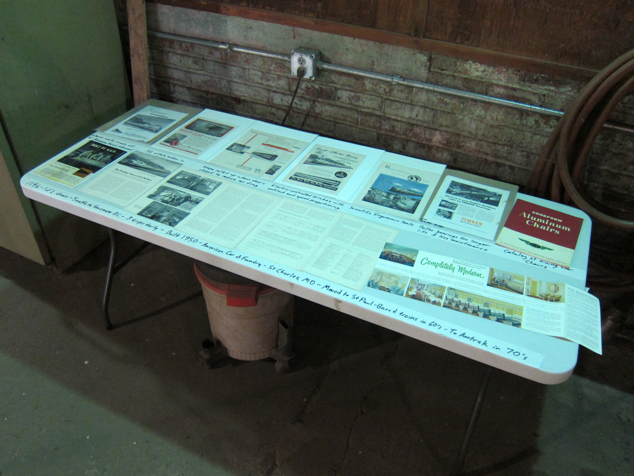 | 1146 as exhibit: Since my work area is right in the aisle, I put together this little exhibit for museum guests on shop tours. The top row is advertisements whose products when into 1146, and the bottom row includes contemporary magazine reviews and advertisements of the new train. |
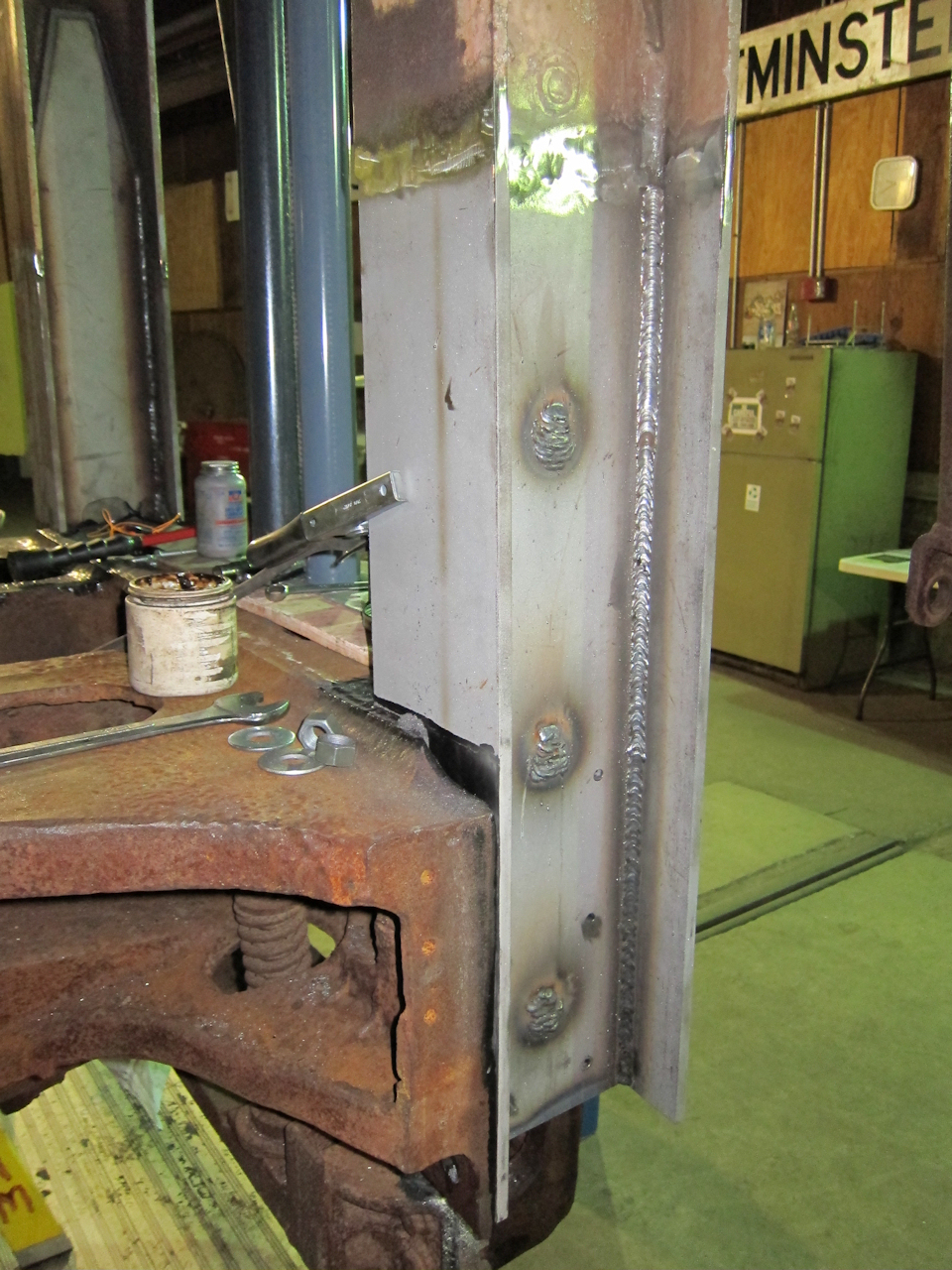 | Shear post section, welded in on the BL collision post. |
 | Another weld detail. BL collision post. |
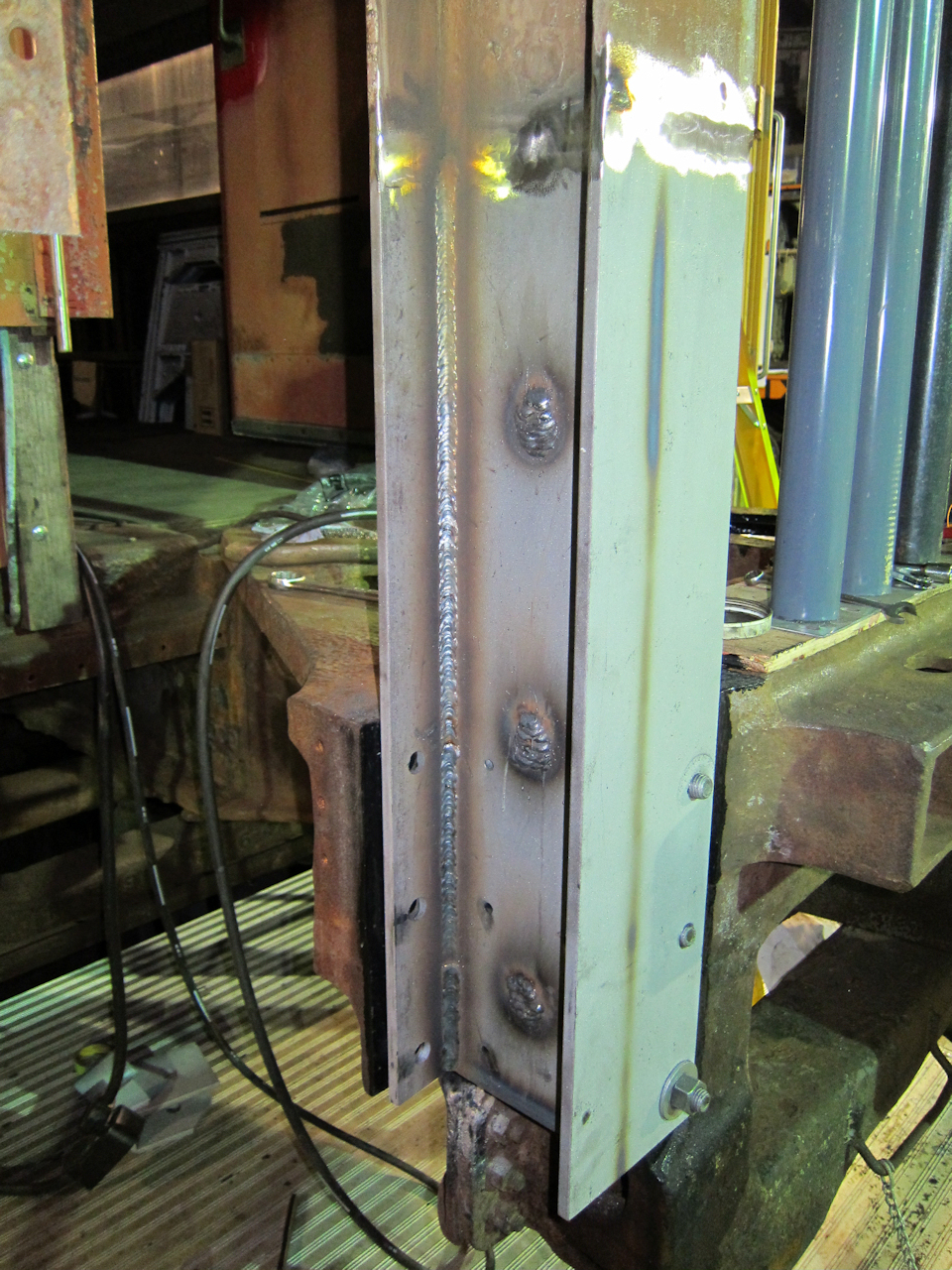
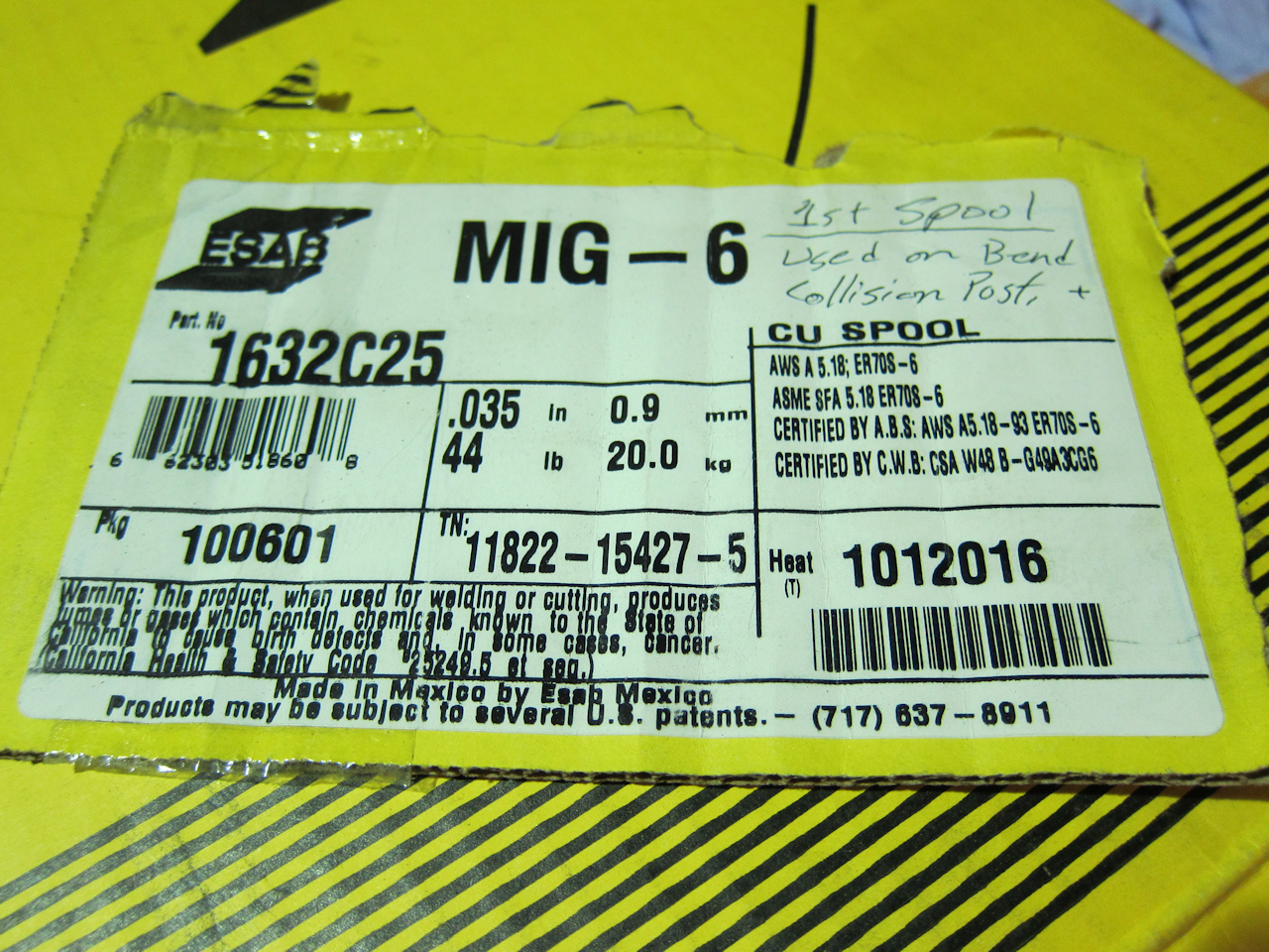 | For the record, this is the tech info on the welding wire used in the collision post welding this year. |
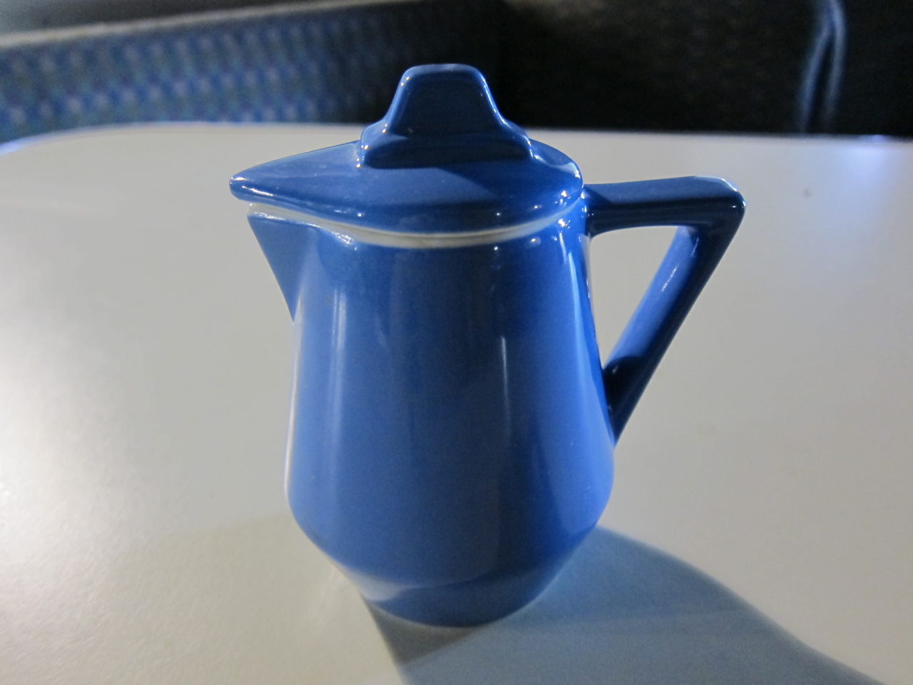
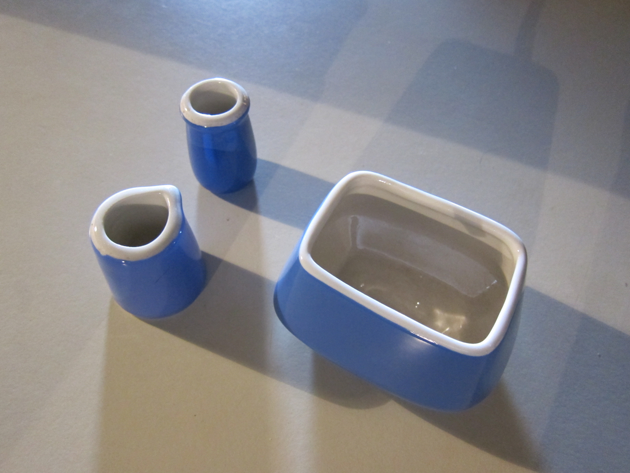
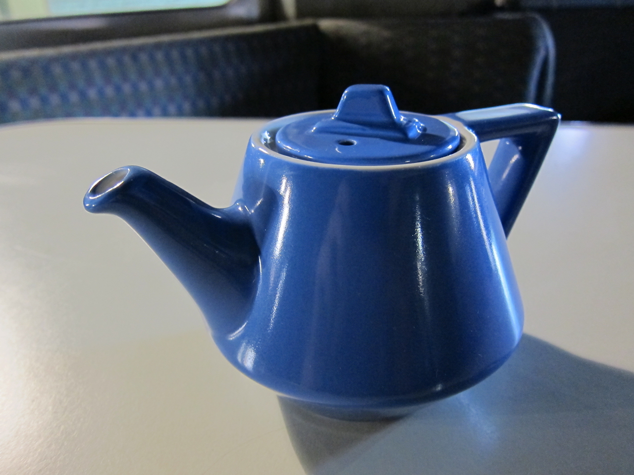 | Here's the latest bit of Amtrak "National" china I've collected. Notice how the teapot color matches the upholstery. These were stock patterns, but the color was custom for Amtrak. |
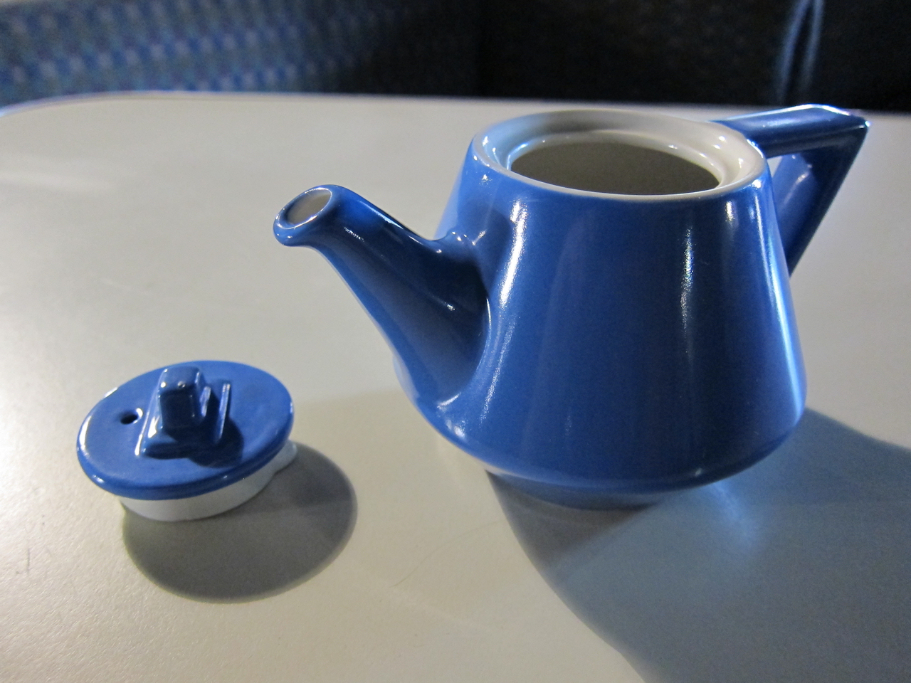 | Again, with the lid off. Look back at February - There's a good chance this sort of teapot belongs with the lid which started this collecting, which I found hidden in a back corner of 1146's kitchen. |
 | I also found this little cream pitcher. (It's barely four inches tall.) Both came from eBay. |
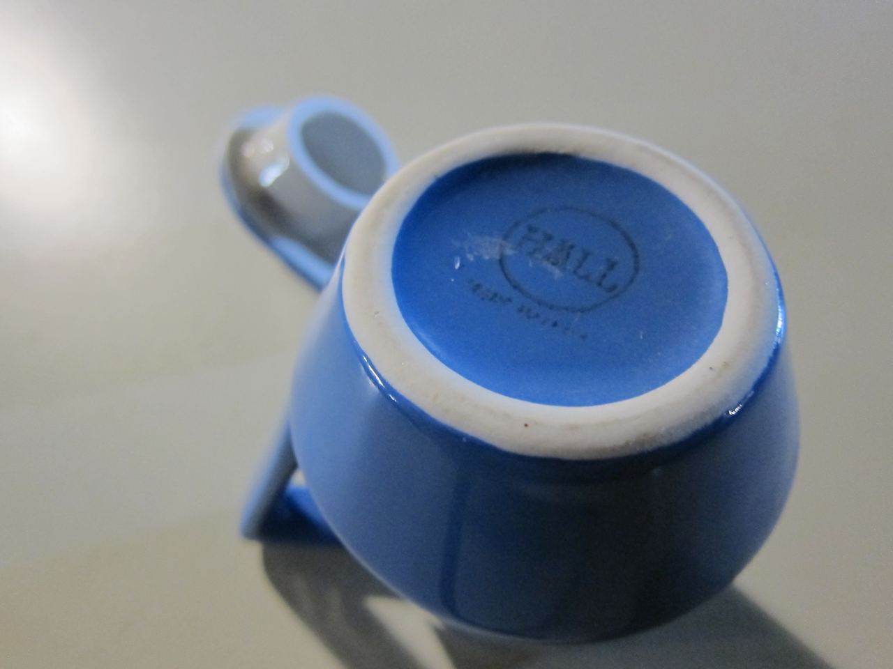 | The teapot's backstamp is illegible, but the cream pitcher's clearly identifies the manufacturer, Hall China. Again from February, here's what the Restaurant Ware Collectors Network tells us about this china pattern. |
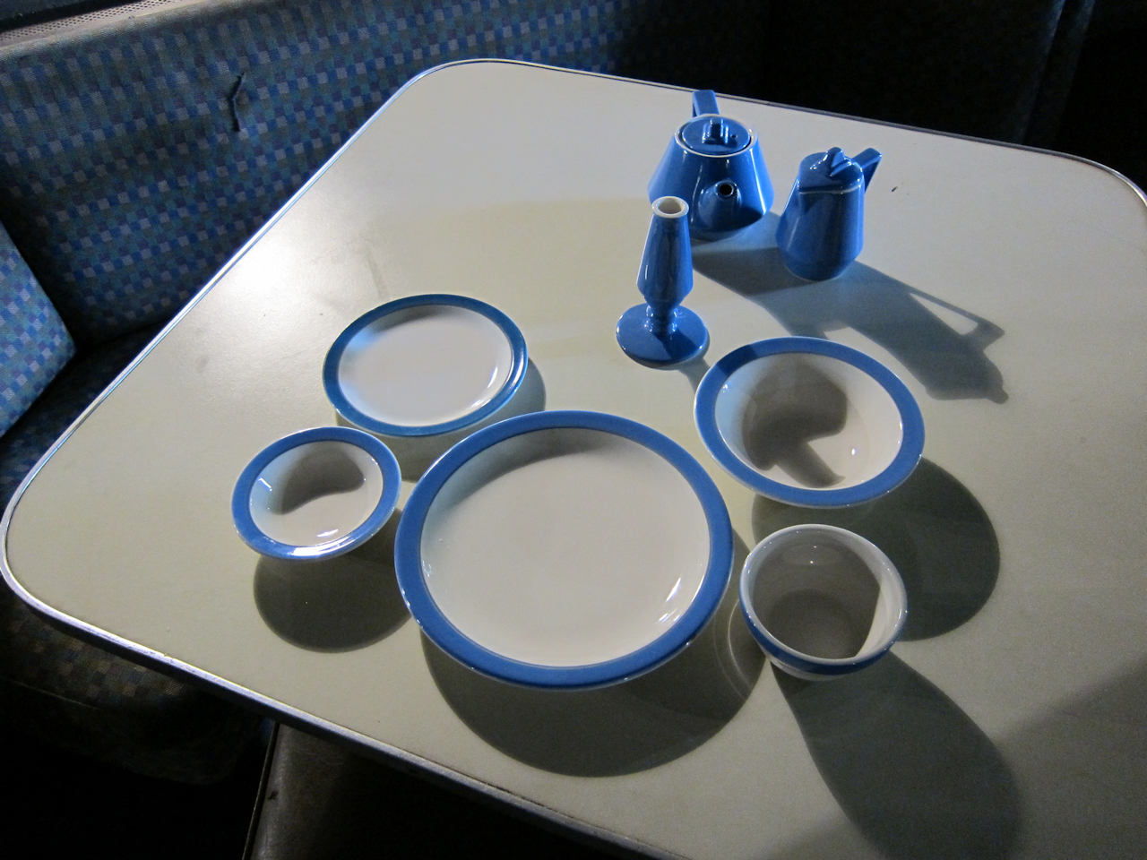 | Here's everything I've collected so far. Still looking for the coffee pot, teacup, and a couple other items. |
Here is the range of grips required for the collision post fasteners - as seen from the B end of the car.
| BL Post | BR Post | ||||||
|---|---|---|---|---|---|---|---|
| 1 11/16" | 1 1/2" | 1 9/16" | 1 3/8" | 1 3/8" | 1 9/16" | 1 1/2" | 1 5/8" |
| 1 3/8" | 1 1/2" | 1 5/8" | 1 1/4" | 1 3/16" | 1 9/16" | 1 1/2" | 1 5/8" |
| 1 1/4" | 1 7/16" | 1 1/2" | 1 1/8" | 1 3/16" | 1 9/16" | 1 1/2" | 1 3/8" |
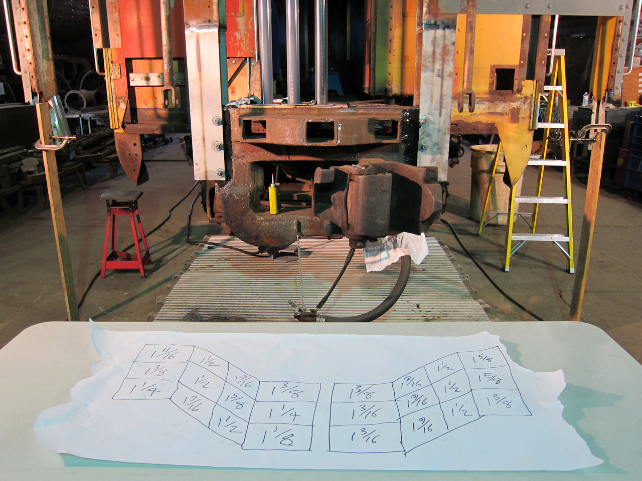 | My "notepad" for recording rivet hole depths. The center two columns are the visible bolts. |
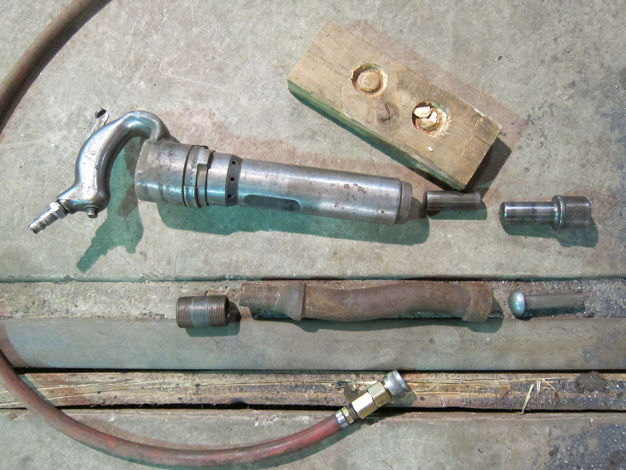 | The museum's air hammer was last used in the late 1990's when steam loco NP 328 was running. Air tool oil and patience proved enough to resurrect it. In this picture, the wood block I killed testing, the Chicago-Pneumatic air hammer with 1/2" quick-connect, it's piston, an Ingersoll-Rand rivet set, a 1 1/4" schedule-80 pipe nipple, an offset set, and a 3/4" hot (solid) rivet. Turns out 1 1/4" sch-80 has the perfect inside diameter to hold a rivet set, perfect for fabricating creative around-the-corner bucking bars. |
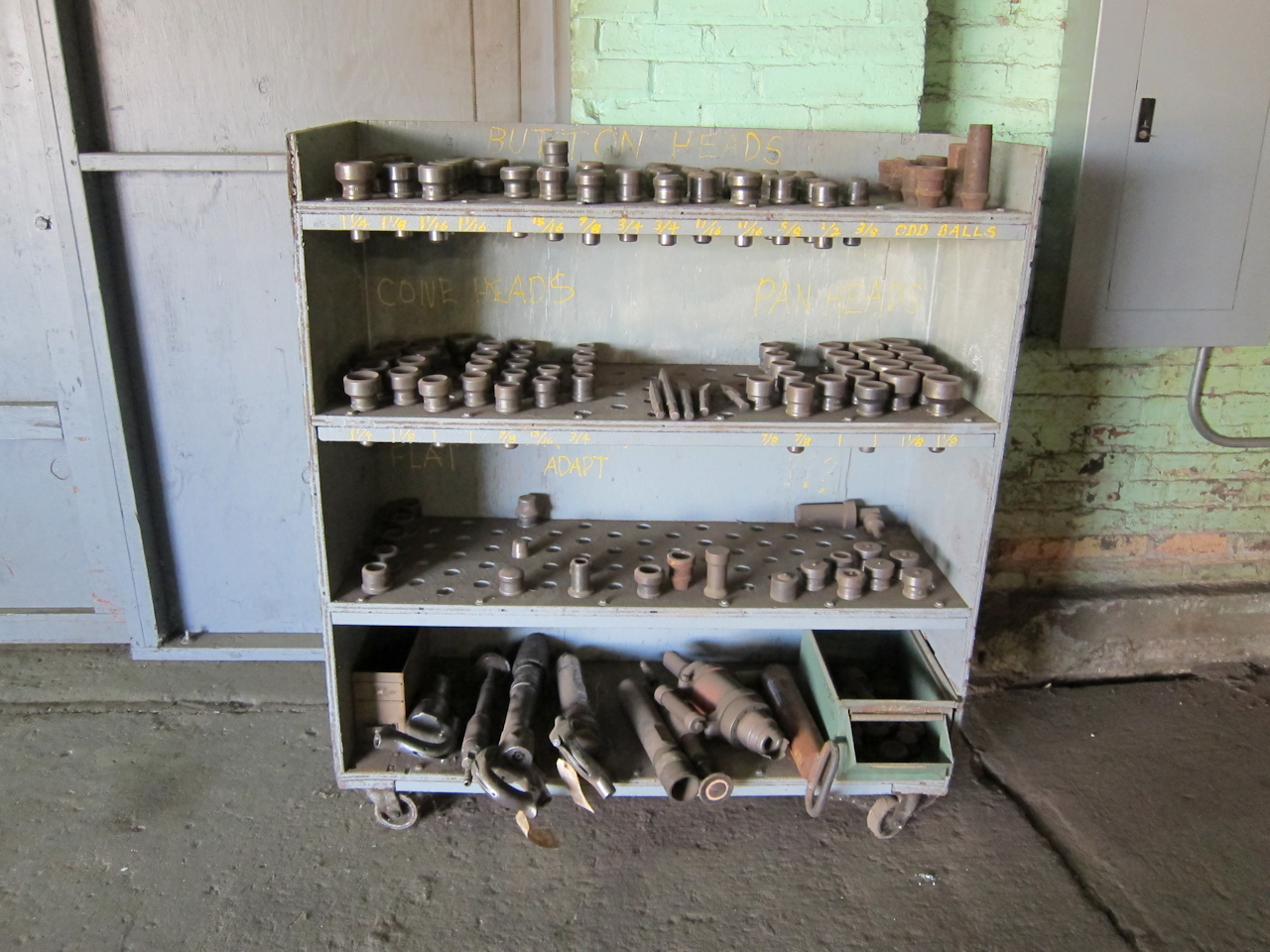 | The museum's hot riveting tools, in all their glory. Not shown is the fire-brick lined rivet forge on wheels, fired by fuel oil and compressed air. |
This year AREMA, REMSA, RSI and RSSI combined their annual conventions in Minneapolis. I had the chance to explore the vendor exhibits, which covered a couple football fields indoors and outdoors.
Starfire was there, and Andrew Spurlock my engineer took time to come inspect 1146. He liked my workmanship on the collision posts, and we talked for a bit about the best fasteners to use. He doesn't like hot rivets because their tensioning is hard to control. He prefers Huck bolts or even structural bolts for their predictability. I have two, maybe four that I probably cannot Huck, and I'm concerned that threaded bolts might come with a periodic inspection requirement. He is going to provide me with a written spec for grade, torque, and permanent thread locking, for use where its impossible to Huck.
I also talked to Andy about doing the side sill engineering this winter.
Alcoa was there showing their Huck fasteners. I looked at the C50L LockBolts, which railroads have been using for car repair in lieu of hot rivets for over fourty years. They were demonstrating their new Bobtail LockBolts, which fill the same niche but have the option of cold, hydraulic removal. I was very interested in their Magna-Lok blind rivets, which look promising for repairing roof eaves. Finally, they touted their BOM blind rivet as being equal in strength to a C50L of the same size. (Actually, they have higher shear strength but lower tensile strength.)
Stucki was there. Their signage and sales rep said that they bought Alco Spring a couple years ago. I haven't seen that reflected in the marketing materials, though.
I spoke with Tom Casper, Vice President of rail sales & marketing of Hadady Corporation. He told me that they inherited a large collection of ASF drawings for passenger car suspension parts.
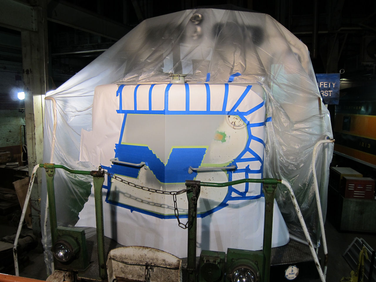
Transhield was showing their train-wrap material, which BNSF uses to store locomotives. It has an outer plastic layer which repels rain but allows vapor to escape, and an inner non-woven strength layer. You specify the vehicle, and they sew to suit. After securing with cinches, a heat gun shrinks the fabric tight - this can be done two or three times, allowing some reuse. If desired they can sew in zippered access doors.
Alan Buchanan, Chief Engineer - Rail, was there from Timken. We talked about their old oil-bath and grease-filled enclosed bearing designs. He hinted (not officially) that he might be able to dredge up drawings for those old designs.
W. E. Lott Company was showing some of their smaller castings. I did a double-take - one was the outer support casting for a streamlined passenger car's vestibule trap door. The sales rep said its not cataloged but they do make a handful of passenger car castings.
I talked to a couple radio vendors, to learn more about the upcoming narrow-band conversion. Bottom line: New 100-channel DTMF locomotive radios cost around $3000, while handhelds and 12v vehicle radios cost around $800. Later I discovered these resources on my own: Ken Fitzgerald's Radio Frequencies page includes an excellent list of AAR Channel Assignments, in which he lays the original 25Khz channels with 15Khz spacing along side the new 12.5Khz channels with 7.5Khz spacing. Vendor Railcom also has a helpful dissertation on the science and implications of narrow-banding, along with a list of radios that will become obsolete and links to authoritive Federal documents. See also the Code of Federal Regulations, Title 47, Part 90, subparts 203 and 209 especially. (This is relevant to 1146, because I'm thinking about hiding a 100-channel DTMF radio in the electrical cabinet for operational convenience.)
Later in the month, I wrote Mr. Burshtin at Amtrak about threaded structural bolts. According to Private Car Notice 2-11, as of September 14th 2011 he has a new role, and Billie J. Ernest & Lee Trombecky have assumed the private car duties.
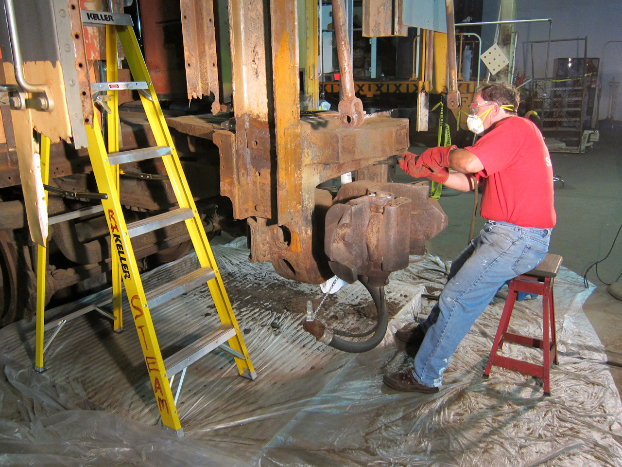
Based on my conversation with Starfire, (and crossing my fingers that Amtrak approves,) I went ahead with Huck Bolts on the collision posts. I was able to reach ten of twelve on each post. The four remaining did not have clearance for the gun so the temporary grade-5 bolts will become permanent, with nuts welded to the bolt threads. Here is a video I made while applying the bolts:
A special shout-out to Tom Rice at Champion Charter Sales & Service in St Paul, who at great inconvenience to himself made sure I had the Huck bolts and tooling I needed. Thank you, Tom, I wouldn't have progressed this far without your help.
 | The rented Huck 940 PowerRig in its shipping case. |
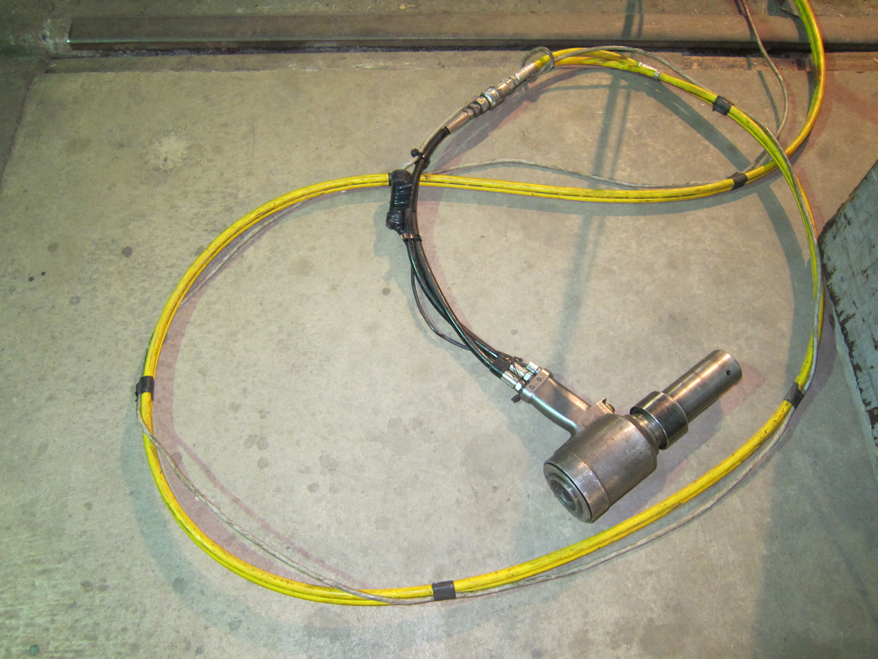 | The rented Huck gun, nosepiece and hose. The nosepiece is specific to the fastener and diameter. The gun can handle a limited diameter range. Press the trigger switch to pull the bolt. After it breaks, release the switch to eject the pin tail. |
 | Three bolt lengths were needed: 16/16", 20/16" and 24/16" - 1/4" increments, with a grip range of +5/16". The 20's were out of stock, but they had some in back that had been galvanized for another customer who later changed their mind. |
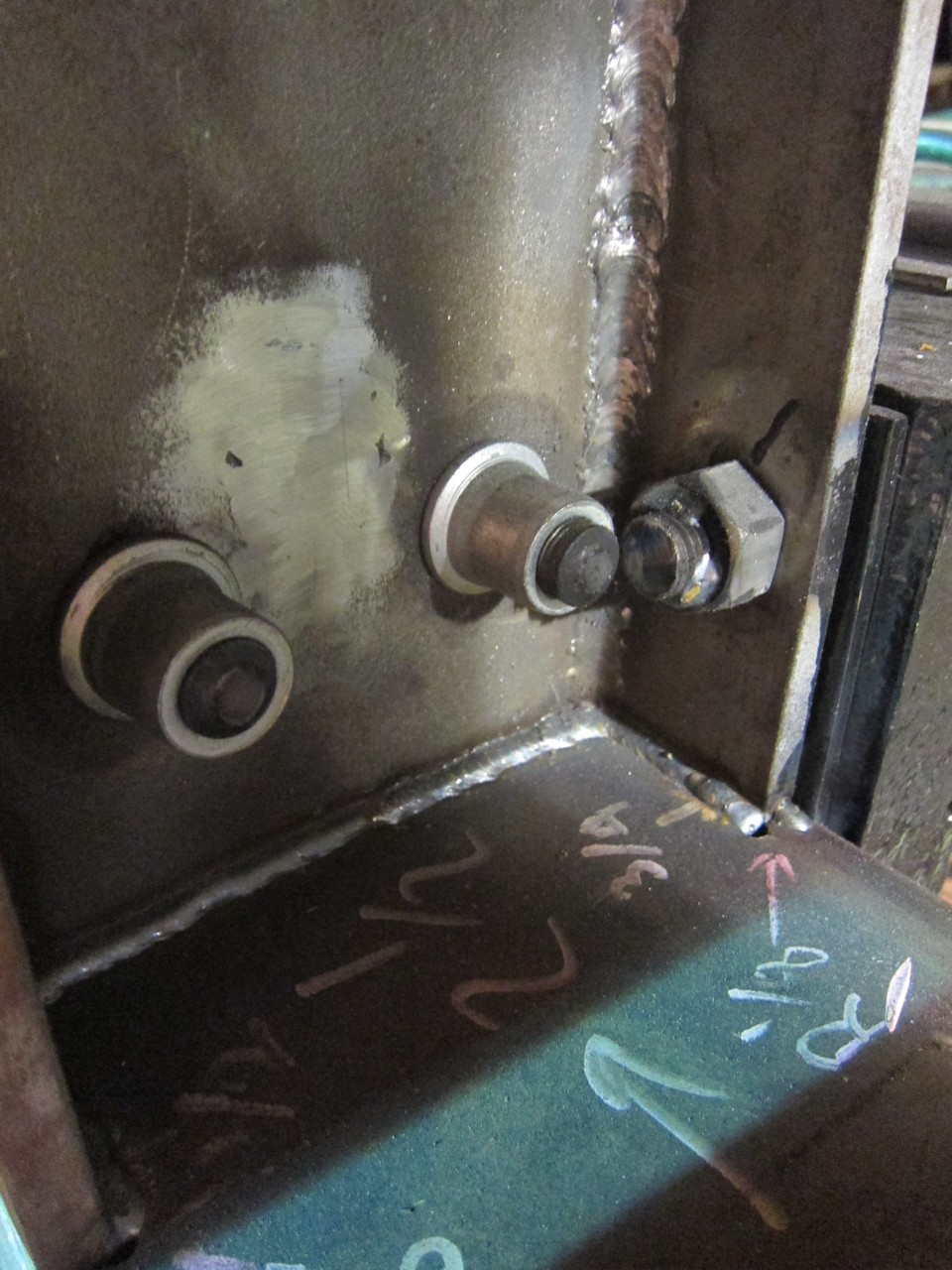
 | Tom Rice had once worked for Loram - the people who custom-build and operate articulated rail-grinding trains - and he persuaded me to use the flanged collars rather than the normal ones. "That's what we always used at Loram." Note the two remaining grade-5 bolts, where the end casting obstructs. There was no way to wiggle the Huck gun in there. Their nuts will be welded to the bolt threads. |
 | Yet more Amtrak "National" pattern china. |
Linders Specialty delivered more Cor-Ten fabrications:
North Second Street Steel Supply delivered three 4'x10' 12 gauge sheets for skinning the end, along with an 8" x 11.5 lb C-channel beam for the top step risers. I should have everything needed for the October work session now.
I hired Matt Arnold of Lake Superior Companies to help for five days. With two of us working, we got a lot done.
 | Since the collision post fasteners get buried, they had to be finalized. My engineer specified grade-5 structural bolts with nuts welded on. (Quoted in italics below.) Note that because I could not get a closed box wrench on the nut due to close clearances, an open-end wrench nearly made the ultimate sacrifice - the cheater bar I found was about 48" long. |
Here is a summary of my engineer's instructions for the structure bolts. I present it here to document the procedure used.
Use ASTM A325 Type 1 bolts with ASTM A563 Grade C Heavy Hex Nuts. No thread lubrication should be used. Do not use galvanized nuts or bolts. Size the length of the bolt for approximately 3 threads to be exposed once the bolt is fully tightened.
As far as torque for application, even though commonly done, industry recommendations are to not use formula-derived torque values, due to the many variables operative on the threads and other surfaces that affect clamping. For structural application, AISC recommends the following procedure to tension the bolts to within 70% of the minimum tensile strength of the bolt: This is called the Turn-of-the-nut procedure:
I had not heard the term "refusal" used before. I also wanted clarification on use of flat washers and the method of locking the nut:
Refusal is an old bridge building term, that originated with driving piles into the ground for bridge pier erection. The pile driver (back in the old days, simply a specially configured steam hammer) would hammer away at the top of each post, or pile, and thus drive it into the ground. When the pile would no longer advance into the ground, this was considered to be the point of refusal (the pile would "refuse" to go further).
When you turn a nut to refusal, you apply moderate but not extreme effort to an end wrench and turn the nut to refusal (where it will not rotate further), snugging everything together. At that point, apply the match marks and then turn the nut further with a wrench and an extension (for better control) to the required rotation. The reference for an impact wrench is an alternative way to snug everything up if you do not want to use the end wrench method. Either way, you make everything "pretty tight" as you mention below.
Yes, I would weld the nut to the threads, with a pair of substantial weld tacks. You should not need a lock nut or lock washer.
Flat washers are usually not used, unless you have problems with galling of the bearing surface under the nut.
A trick that worked out well - and I wish I'd brought the camera - was using pickets and a string line to align the HSS box tubes that form the bottom of the vestibule end wall. The idea came from helping my Uncle lay out an addition to a house: Just beyond each end of a wall, pound two stakes ("pickets") into the ground. Screw on another stake to form an "H". Stretch a string from one crossbar to the other. Do this for each side, and you can mock up the foundation and get it perfectly square before building anything. For 1146's vestibule end sill, we stretched one string from one portable work light to another. First we adjusted them so the string just brushed against each collision post. Then we adjusted the height at each end so that the string was square to the collision posts. That gave us a guideline for squaring up the end sills on blocking. A regular framing level would have been useless since both the track cross-level and 1146's suspension are suspect. Also note that I could not extend a string from the bottom of the frame, since the body end sill actually hangs an inch below the side sills.
 | The steel shapes designed by StarFire and fabricated by Linders Specialty went together pretty quickly. Note that the aluminum trim around the vestibule door will have to be replicated. Also, the bottom of the vestibule end is about one inch higher than it used to be, to account for the Amtrak COMM and MU recepticles. |
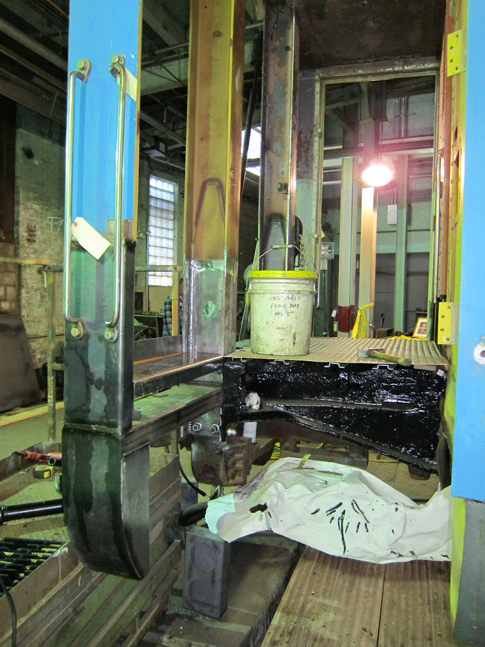 |
To get the elevation of the vestibule end sill's top halves set correctly, we temporarily set the original stainless stell vestibule platform on the new Cor-Ten joists. The bucket of used floor-dry was for weight, to assure it wasn't springing up and throwing us off.
Per ACF's original blue prints, a 3/8" tapping plate was welded inside the 1/8" corner post, so that the grab iron bolts would have enough threads to screw into. Use plenty of thread cutting oil - if the tap squeaks it is either dull or too dry. |
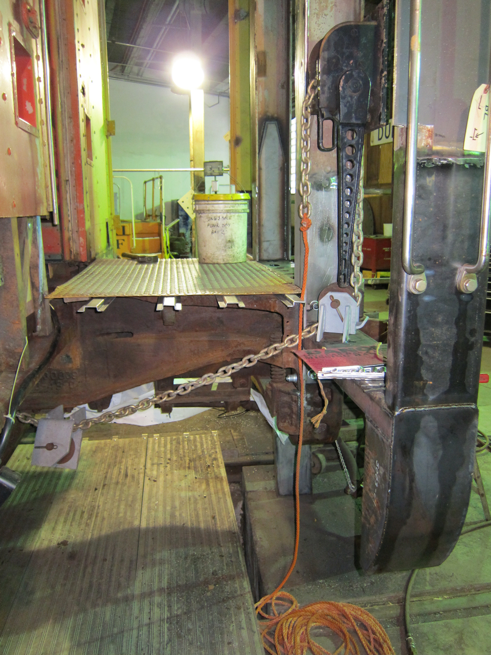 | The upper hand brake sheave wheel had to be welded in before the end sill's top went in. Originally it hung below the end sill, where the Amtrak COMM and MU recepticles will be. |
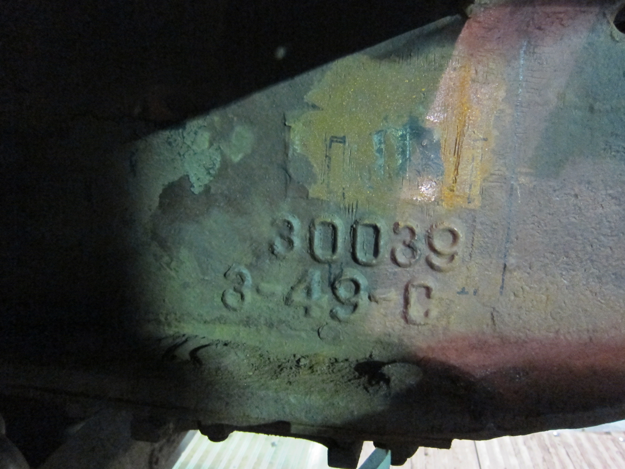 | One last photo of the end casting number and date. The black pen marks show where the lower hand brake sheave wheel will be welded on - it had to be tilted, which lowered it's back end. |
I've heard many warnings about welding to cast iron: Pre heat, post heat, use Nickel rod, peen the weld while still hot. So I went and got a piece which I knew to be cast iron (because milling it created graphite powder, rather than chips) and a piece of low-carbon steel, and compared their grinder sparks with the end casting. The end casting's sparks were like the steel. Even so, I Googled "welding to cast steel" and looked at some welding text books. That was confusing - most people seem to confuse cast steel with cast iron. In fact they are very different. Cast iron contains approximately 4% carbon - far more than can bond with the iron to create Cementite molecules in Pearlite structures - so the excess carbon is embedded in the iron as graphite. Cast iron is relatively hard and brittle, likely to crack under the strains imposed by weld filler metal shrinking as it cools. Pre-heating helps because it actually expands the cast iron. Post-heating, also known as slow, controlled cooling, helps because it gives the stresses time to disappate. High-Nickel weld filler metal helps because Nickel is more ductile than iron, and does not shrink as much. (Warning - I'm told Nickel is very poisonous.) Peening helps by actually pounding the weld into a thinner mass with more surface area. In the end, I learned that a mild pre-heat of 150 to 450 degrees farenheit and peening the hot weld can't hurt.
Here's what my engineer advised:
Do some localized preheating of the casting to 150 degrees F before welding, and keep it at that temp till welding is finished. You should have less problems with cracking of the welds. Castings can be tricky.
 |
From left to right, the tools I used to weld to the end casting:
|
 | Here's how it looks after welding. |
 | Because the sheave wheels were moved, I had to shorten the hand brake chain. Here it is fully tightened. Loose, the stop is against the mechanism and the chain droops about five inches. I tapped the wheels with a ball-peen hammer to verify: Loose, they ring like a bell. Tight, they give a dull thud. |
I'm thinking about replacing this hand brake mechanism. The chain guide that covers 180 degrees of the sprocket wheel is loose, flops around, and gets in the way when I try to thread a rope for pulling the chain through. There is also a clearly after-market bolt in the side to keep the guide somewhat positioned. Not the level of quality I'm looking for - but at least it doesn't self-release when wound tight. That can happen when the sprocket teeth and dog get worn to a negative angle, so that tension kicks the dog out rather than pulling it further in.
Hint: To install the chain in a Peacock model 800 lever-style hand brake like this one, first thread a rope through in reverse. Tie it to the end of the chain and pull the rope as you run the ratchet handle. Also, make sure the chain is not twisted. If it is it the twists will bind up between the chain guide and the sprocket. The weight is three pieces: A cast weight with a slot for the last link, a pin, and a rubber collar which helps capture the pin.
Interesting trivia: Steel's Eutectic point - the lowest temperature at which steel is entirely liquid, regardless of carbon content, is 1146 degrees celcius (2095 degrees farenheit) and occurs at 4.27% carbon. The other critical temperature is the Eutectoid point - the lowest temperature at which molecular changes start to occur in solid steel. Heating steel past this point allows one to change its hardness. It is 727 degrees celcius (1341 degrees farenheit) and occurs at .77% carbon. Neat - 727 and 1146 are two numbers I can remember!
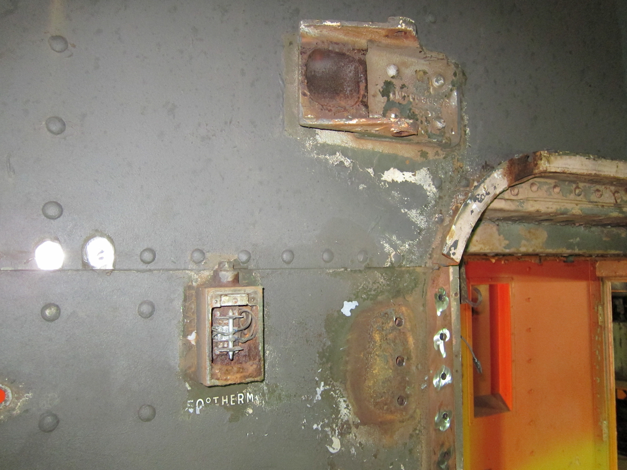 | I had always wondered why there was an abandoned electrical junction box on the outside of 1146's B end. Mystery solved! It was the outside temperature thermometer, set to turn on at fifty degrees farenheit. |
 | We left the old end sheets on to provide diagonal bracing to the corner posts, until their bottom ends were secure. Then we put new end sheets on. A forklift is a great tool for lifting end sheets into position. |
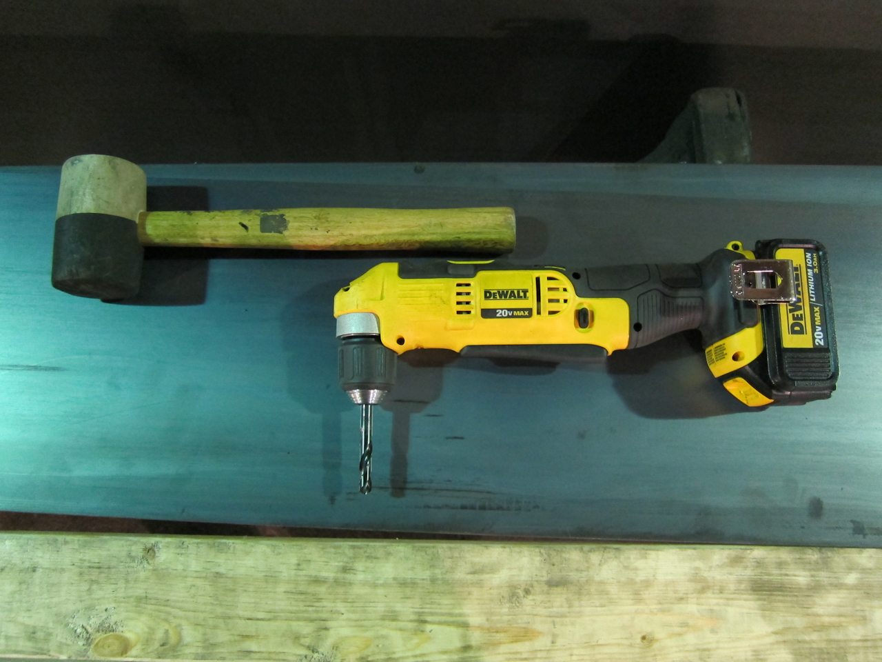 | Tools used for drilling rivet holes in the new end sheets, using the existing holes in the collision posts and corner posts as guides: A low-profile right-angle drill, a stubby split-point drill bit, and a hammer. The hammer handle was used as a lever to put significan pressure on the drill - don't forget to lube the bit regularly with cutting oil! |
 | I had an opportunity to acquire 26-C brake equipment off a Long Island commuter coach that was being scrapped. 1146's D-22 is still accepted by Amtrak, but the valves are heavy, they use lapped slide valves, must be serviced every 24 months and are more costly to maintain. 26-C is still current technology, uses diaphragms and o-rings, and gets serviced every 36 months. |
Because I need to learn HTML5 and it's related standards at work, this web site is morphing from my simple handwritten HTML 4.01 Transistional. Some colorful formatting may slip in as I experiment. Tools include:
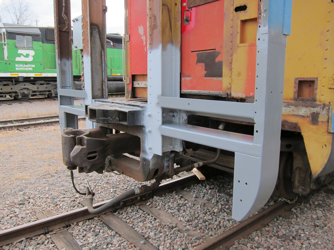 | The museum needs the indoor shop space so I quick shot my new steel with rattle cans. There is a bit more welding, then I can sandblast, prime with Corlar epoxy primer, and rivet the end sheets on. |
 | Some of the detail work: Sharp steel corners ground to a micro-radius so that the paint will be less likely to chip, and tapping plates added where ever trim will be screwed on. |
 |
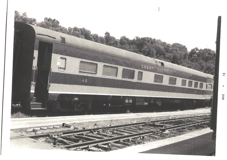
I found this picture of twin sister Amtrak 8400 by Michael Palmieri on rrpicturearchives.net, and added a link to 1146's Amtrak history. If anyone knows how to contact Mr. Palmieri, I'd like to thank him. |
Someone might find the archives of the Norfolk & Western Historical Society interesting. They have scanned many passenger car drawings, including construction drawings and detail drawings for small parts.
A friend pointed me to a GN Trains website. They are a passenger car rebuilding contractor, and have done some interesting problem solving and offered the results to us.
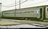
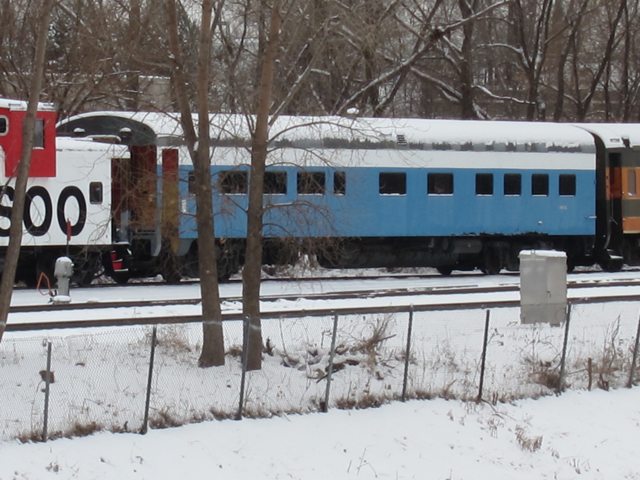 | It's December in Minnesota and Santa Claus has come to town. Some cars got pushed out to "end of track" to make room for Santa's train. This photo was taken from a city street on the north side of the GN main. Big Sky Blue looks awesome in the snow. |
 | Another view from the Rice Street bridge. The cars are on a remnant of the GN's four-track main - specifically the eastbound freight main. Westbound freight is the access road. The passenger mains survive. |
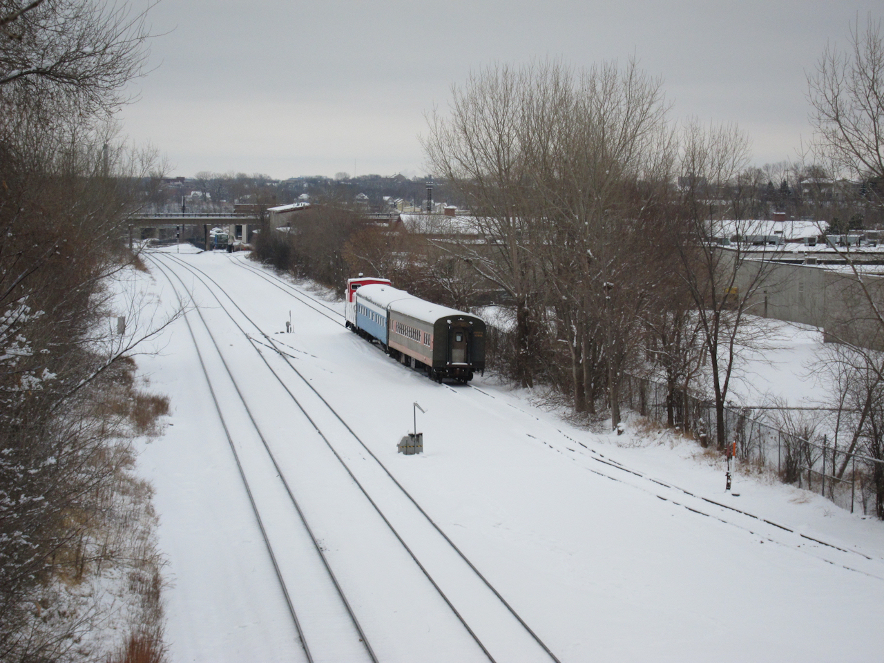
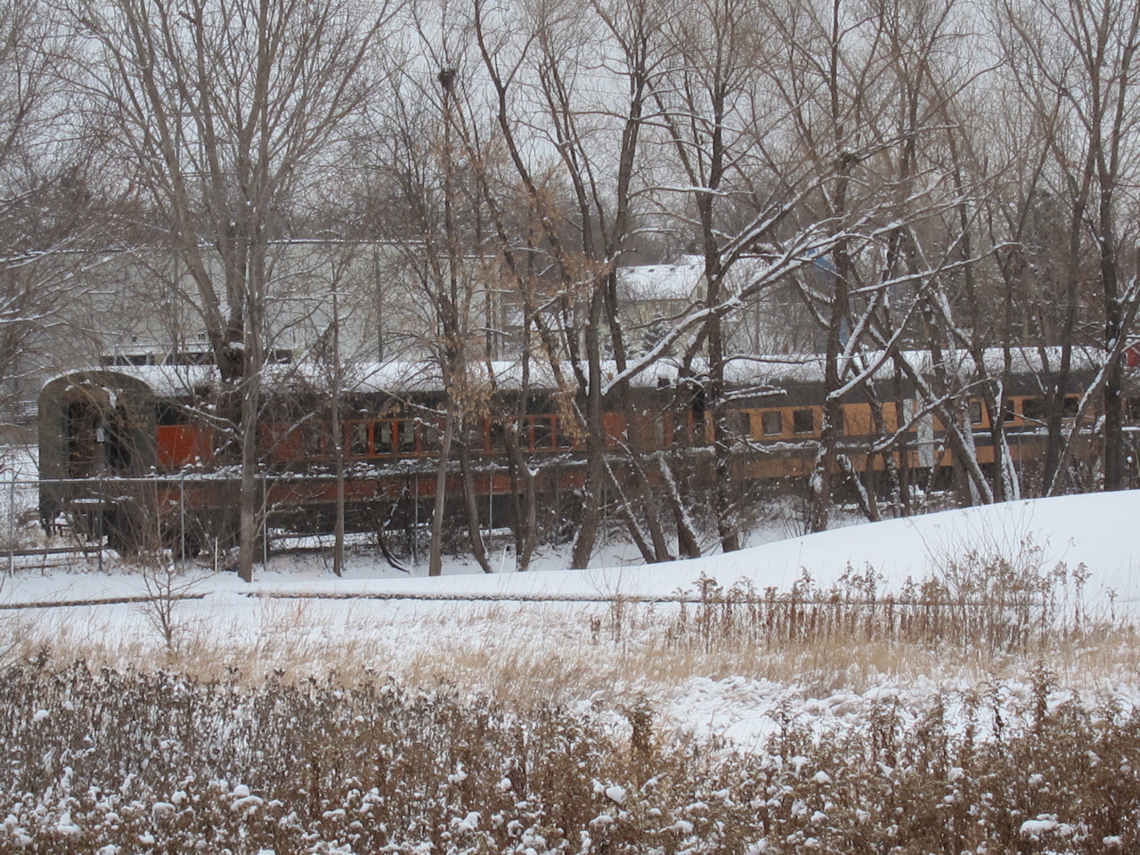 | The tree line on the south side has grown up over the years, making for terrible photographs but rather romantic views. What railfan wouldn't want to stumble upon Empire Builder colors hidden in the woods? |
 | While 1146 was cooling it's heels, I did a partial Empire Builder job on GN 1097 - former CNW 3444. |
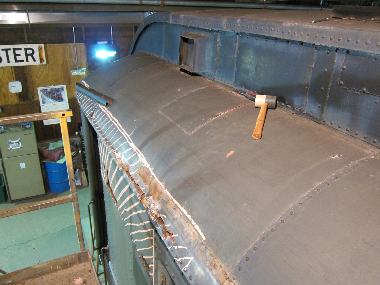 | Next I started steelwork on NP triple-combine 1102. This 1914 beauty started life as Pullman's "Reba". Most of the damage seen was caused by water leaking in the far joint in the lower roof. The near sheet was pre-drilled for rivets - in the wrong spot - and the caulk eventually failed. |